


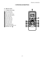
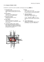


7-2-1. Louver control
(1) Vertical air flow louver
Position of veritcal air flow louver is automatically
controlled according to the operation mode.
Besides, position of vertical air flow louver can be
arbitrarily set by pressing [FIX] button.
The louver position which is set by [FIX] button is
stored in the microcomputer, and the louver is
automatically set at the stored position for the next
operation.
(2) Swing
If [SWING] button is pressed when the indoor unit
is in operation, the vertical air flow louver starts
swinging. When [FIX] button is pressed, it stops
swinging.
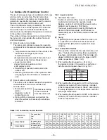
7-2-2. Indoor Fan Control
The operation controls the fan speed at indoor unit
side. The indoor fan (cross flow fan) is operated by
the phase control induction motor. The fan rotates in 5
stages in MANUAL model, and in 5 stages in AUTO
mode, respectively. (Table 7-2-1)
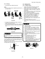
1) When setting the fan speed to L, M or H on
the remote controller, the operation is performed
with the constant speed shown in Fig. 7-2-1.
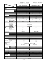
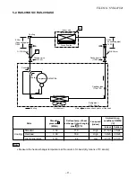
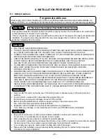
7-2. Outline of Air Conditioner Control
This is a fixed capacity type air conditioner, which uses
a AC motor for an indoor fan. The AC motor drive
circuit is mounted in the indoor unit. And electrical
parts which operate the compressor and the outdoor
fan motor, are mounted in the outdoor unit.
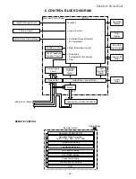
The air conditioner is mainly controlled by the indoor
unit controller. The controller operates the indoor fan
motor based upon commands transmitted by the
remote control and transfers the operation commands
to the outdoor unit controller.
The outdoor unit receives operation commands from
the indoor unit, and operates the outdoor fan motor
and the compressor.
(1) Role of indoor unit controller
The indoor unit controller receives the operation
commands from the remote control and executes
them.
•
Temperature measurement at the air inlet of the
indoor heat exchanger by the indoor
temperature sensor
•
Temperature measurement of the indoor heat
exchanger by the heat exchanger sensor
•
Louver motor control
•
Indoor fan motor operation control
•
LED display control
•
Transferring of operation commands to the
outdoor unit
•
Receiving of information of the operation status
and judging of the information or indication of
error
(2) Role of outdoor unit controller
The outdoor unit controller receives the operation
commands from the indoor controller and
executes them.
•
Compressor operation
control
•
Operation control of
outdoor fan motor
•
Turning off the compressor and outdoor fan
when the outdoor unit receives the shutdown
command
Operations according
to the commands
from the indoor unit
L
M
W6
W9
WC
Indication
Fan speed
the setup temperature, room temperature, and heat
2) When setting the fan speed to AUTO on the remote
controller, revolution of the fan motor is controlled
to the fan speed level shown in Table 1 according to
exchanger temperature.
Fig (7-2-1)
WF WE WD WC WB WA W9 W8 W7 W6 W5 W4 W3 W2 W1
UH H M+ M L+ L L- UL SUL
UH
H
M+
M
L+
L
L-
UL SUL
fan speed (rpm)
Air flow (m
3
/h)
fan speed (rpm)
Air flow (m
3
/h)
Dry
Cool
Fan speed level
M
odel
RAS-07SKSX
RAS-09SKSX
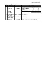
Table 7-2-1 Indoor fan and air flow rate
FILE NO. SVM-07021
1300
1300
1300
1300
1250
1150
1100
950
950
900
800
750
700
650
500
540
540
540
540
510
470
440
370
370
350
300
270
250
220
150
1350
1350
1350
1300
1250
1180
1140
1000
980
980
900
800
750
700
550
560
560
560
540
510
500
460
400
390
390
350
300
270
250
180
−
15
−
OPERATION
MODE
3) When setting the fan speed to QUIET on the remote
controller, revolution of the fan motor is controlled
to the fan speed level is L-.
H


