


Configuration Software
Page 50
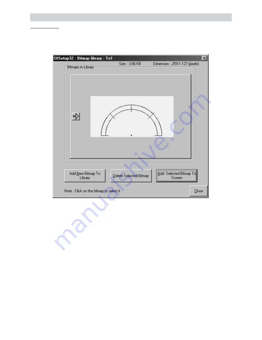
Bitmap Object:
To display a user defined bitmap, click on the Bitmap button. In the dialog box presented user can add
bitmap to library, delete a bitmap from the library or add a library bitmap to screen. User can add any
required bitmap. Any 256 color bitmap can be added to the bitmap library.
Once all the screens are completely defined, user has to define the ‘Power-on Application Task’.
Power-on Application Task is like a boot-up sequence for the unit. Tasks mentioned here are performed
immediately after the unit is powered on.
Here user has to specify the screen to be displayed after the unit is powered on. User can either use
‘Goto Screen’ task or ‘Copy tag to STR’ task. ‘Goto ..’ task will write screen number to Screen
Triggering Register (STR) and display the screen specified by STR. ‘Copy tag..’ task will copy the speci-
fied PLC tag to Screen Triggering Register. Screen Specified by STR will be displayed. Default Power on
task is ‘Go To Screen 1’.
If user wishes to perform some tasks continuously, these tasks should be defined in the Global Task-List.
This completes the application. Now this application has to be saved and downloaded. Global tasks are
not mandatory.