– 18 –
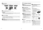
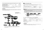
Remote controller sensor
When the indoor unit has a built-in remote
controller, the remote controller sensor is
unavailable.
The temperature sensor of the indoor unit senses room
temperature usually. Set the remote controller sensor
to sense the temperature around the remote controller.
Select items following the basic operation procedure
(
1
→
2
→
3
→
4
→
5
→
6
→
7
).
• Specify
[32]
for the Code No. in Procedure
4
.
• Select the following data for the set data in
Procedure
5
.
When
flashes, the remote controller sensor is
defective.
Select the set data [0000] (not in use) or replace the
remote controller.
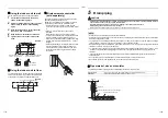
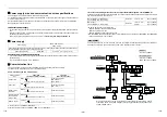
Group control
In a group control, a remote controller can control up to
maximum 8 or 16 units. (Depending on the outdoor
unit.)
• The wired remote controller only can control a group
control. The wireless remote controller is unavailable
for this control.
• For wiring procedure and wires of the individual line
(Identical refrigerant line) system, refer to
“7. Electrical connection” in this Manual.
• Wiring between indoor units in a group is performed
in the following procedure.
• Connect the indoor units by connecting the remote
controller wires from the remote controller terminal
blocks (A, B) of the indoor unit connected with a
remote controller to the remote controller terminal
blocks (A, B) of the other indoor unit. (Non-polarity)
• For address setup, refer to the Installation Manual
attached to the outdoor unit.
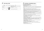
Set data
0000
0001
Remote controller
sensor
Not in use
(Factory default)
In use
9
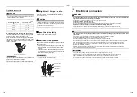
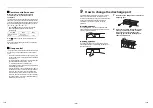
How to change the discharge port
The air discharging direction of the indoor unit has
been set to forward direction as factory default.
However it is possible to change to upward direction.
Change the discharging direction according to
conditions of the room or requirement by the
customers.
In cooling operation
In cooling operation, use the air conditioner with
upward direction of air discharge so that cold air is
spread over the whole room.
In heating operation
In heating operation, use the air conditioner with
downward direction of air discharge so that hot air
reaches at the foot.
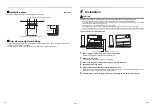
1
Remove the two fixing screws inside of the
discharge port.
2
Insert your hand into the discharge port,
push up the back side a little, and then
remove the hooks at rear side of the
discharge port to lift the discharge port
upward and remove it.
35-EN
36-EN
Summary of Contents for MML-UP0071H-E
Page 30: ...EB99841101 ...

