PROGRAMMING
TMS7 SERIES
ME00070B
19
Adjustment
: Function 3
Minimum Current
and Function 4
Start
Ramp Time
are used together to activate and control the Ramp
Start mode.
If the Ramp Start mode is required, set the
Minimum Current
so
that the motor begins to accelerate immediately a start is
initiated. Ramp Start mode is not required, set the
Minimum
Current
equal to the Current Limit.
Ramp Start mode should be considered in preference to Current
Limit start mode in applications where:
•
Required start torque can vary from start to start. For
example conveyors may start loaded or unloaded. In this
case set Function 3
Minimum Current
to a level that will
start motor in the light load condition and Function 2
Current Limit
to a level that will start the motor in the high
load condition.
•
Starting time of an easily broken away load needs to be
extended, for example pumps.
•
A generator set supply is limited and a slower application
of load will allow greater time for the generator set to
respond.
4.
Start Ramp Time
Range
: 1 – 30 Seconds
Default Setting
: 1 Second
Description
: Sets the ramp time for the Current Ramp start
mode.
Adjustment
: Set the
Start Ramp Time
to optimise start
performance.
5.
Stop Ramp Time
Range
: 0 – 100 Seconds
Default Setting
: 0 Second (Off)
Description
: Sets the soft stop ramp time for soft stopping of
the motor.
Adjustment
: Set the
Stop Ramp Time
to produce the desired
motor stopping performance.
Two soft stop modes are provided by the TMS7. Use Function
10.
Soft Stop Mode
to select the desired mode.
If utilising the Soft Stop function and a line contactor, the
contactor must not be opened until the end of the stop ramp
time. The TMS7 programmable outputs A,B or C can be set for
control of the line contactor. Refer Functions 21, 22, 23 for
programmable output assignment details.
6.
Motor Trip Class
Range
: 0 – 60 Seconds
Default Setting
: 10 Seconds
CAUTION
NOTE:
A setting of 0 seconds disables the TMS7 motor
thermal model. Use this setting only if another form
of motor protection is used.
Description
: Sets the motor thermal capacity used by the TMS7
motor thermal model.
Adjustment
: Set the Motor Trip Class (MTC) according to the
motor’s thermal capacity.
A motor’s thermal capacity is expressed as the maximum time
(seconds) a motor can maintain locked rotor current conditions
from cold, and is often referred to as Maximum Locked Rotor
Time or Maximum DOL Start Time. This information is available
from the motor data sheet or direct from the motor supplier.
CAUTION
NOTE:
The TMS7 motor thermal model assumes a
locked rotor current of 600%. If the connected
motor’s locked rotor current differs from this,
greater accuracy can be achieved by using a
normalised MTC figure. A normalised MTC
figure can be calculated as follows:
Time
Start
Max
X
2
600
%LRC
=
MTC
CAUTION
NOTE:
Setting Function 6
Motor Trip Class
according
to the motor’s actual thermal capacity allows
safe use of the motor’s full overload capability
both to start the load and ride through overload
conditions. Additionally, a more conservative
approach can be taken by setting a reduced
MTC for easy to start loads that will not
experience transient operating overloads as a
part of normal operation.
Using a reduced MTC figure has the advantage
of maximising motor life. The life of a motor is
strongly influenced by its maximum winding
temperature, with a 'rule of thumb' stating that
the expected life span of a motor is halved for
every ten degree rise in temperature. The
temperature rise is dependent on the motor
losses and the motor cooling. The highest
stress on the motor is during start, and can be
minimised by restricting the duration and
frequency of starts. A reduced MTC setting
(Function 6) will also cause the TMS7
protection to operate before the motor is
thermally stressed.
A suitable reduced MTC figure can be
established by observing the modeled motor
temperature as shown on the TMS7 LED
display, and adjusting the MTC parameter such
that after a normal start which has been
preceded by a period of running at maximum
load, the calculated motor temperature is
approaching 90%.
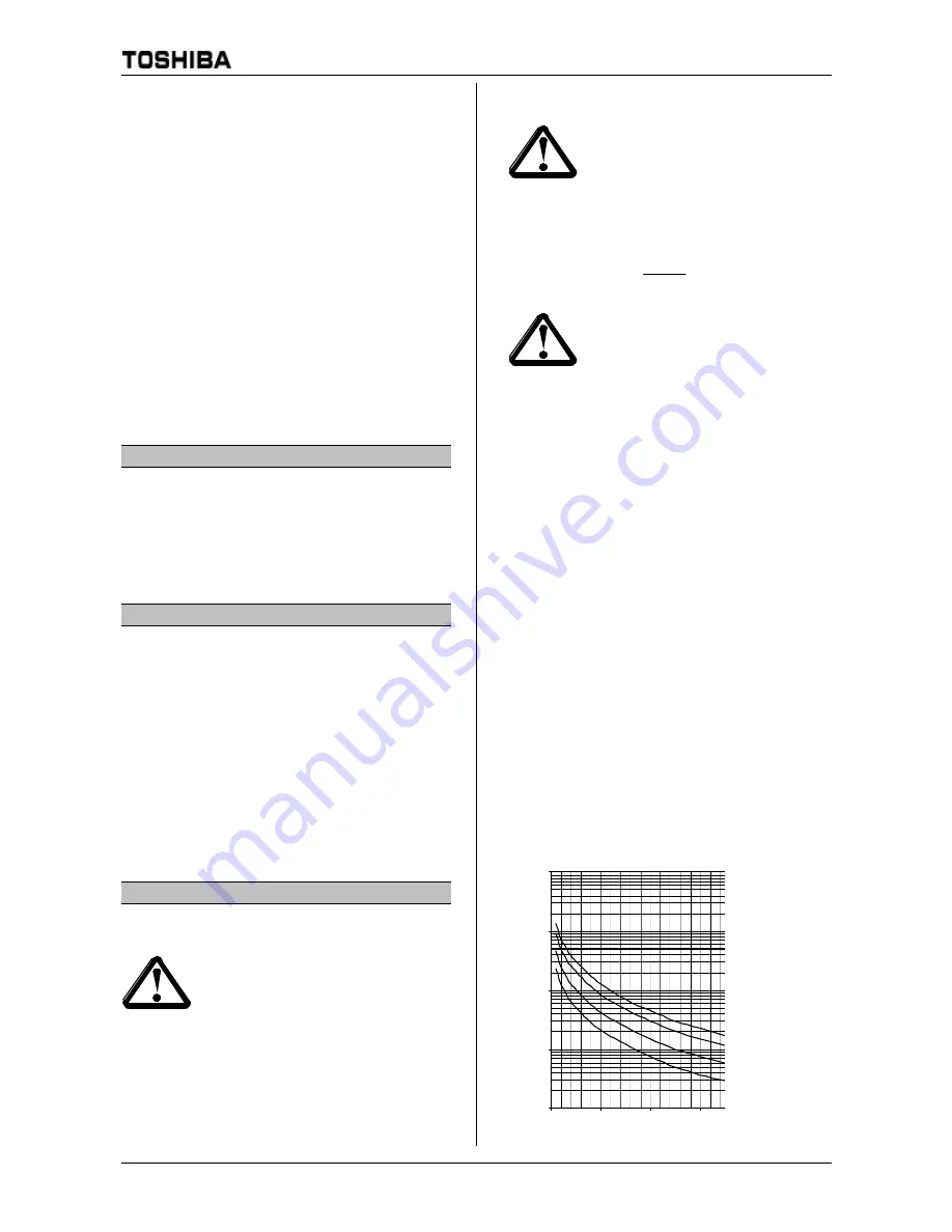
Cold start curves
1
10
100
1000
10000
100
300
500
700
I (% FLC)
t(s)
MTC = 5 Sec
MTC = 10 Sec
MTC = 20 Sec
MTC = 30 Sec


