– 11 –
Hydro Unit
Installation Manual
Water charging
Fill the system with water until the pressure gauge
shows the recommended pressure value of 0.15 MPa
(1.5 bar).
Hydraulic pressure may drop when the trial run begins.
In that case, add water.
Air may enter if the charged hydraulic pressure is low.
Loosen the purge valve cap by two turns to release air.
▼
Fig.7-16
Loosen the cap of the pressure relief valve to release
air.
Water may come out of the pressure relief valve.
Release the air completely from the water circuit.
Failure to do so may disable correct operation.
Water quality
The water used must satisfy EN directive 98/83 EC.
Piping insulation
It is recommended that insulation treatment be applied
to all pipes. To perform optional cooling operation,
apply insulation treatment of 20 t or more to all pipes.
■
Electrical installation
WARNING
WARNING
• Ensure electrical circuits are isolated before
commencing the electrical installation.
• The electrical installation must be completed by a
qualified electrician.
• The electrical installation must comply to all Local,
National and International electrical installation
regulations.
• This product must be earthed in accordance with
Local, National and International electrical installation
regulations.
CAUTION
• The Hydro Unit must be connected to a dedicated
power supply for the back up heater circuit.
• The electrical supply must be protected by a suitably
sized over current protection device (fuse, MCB etc)
and an earth leakage protection device.
• The Hydro Unit must be connected to the mains power
supply using a isolating switch which disconnects all
poles and has a contact separation of at least 3 mm.
• The cord clamps, attached to the Hydro Unit, must be
used to secure the electrical cables.
• Wrong connection of electrical cables may result in
electrical component failure or fire.
• Ensure the electrical cables are sized in accordance
with the installation instructions.
• Check that cabling will not be subject to wear,
corrosion, excessive pressure, vibration, sharp edges
or any other adverse environmental effects.
The check shall also take into account the effects of
aging or continual vibration from sources such as
compressor or fans.
Loosen 2 turns for
proper venting
* Purge valve cap faces the front as factory default.
* The direction purge valve cap may change during
transportation.
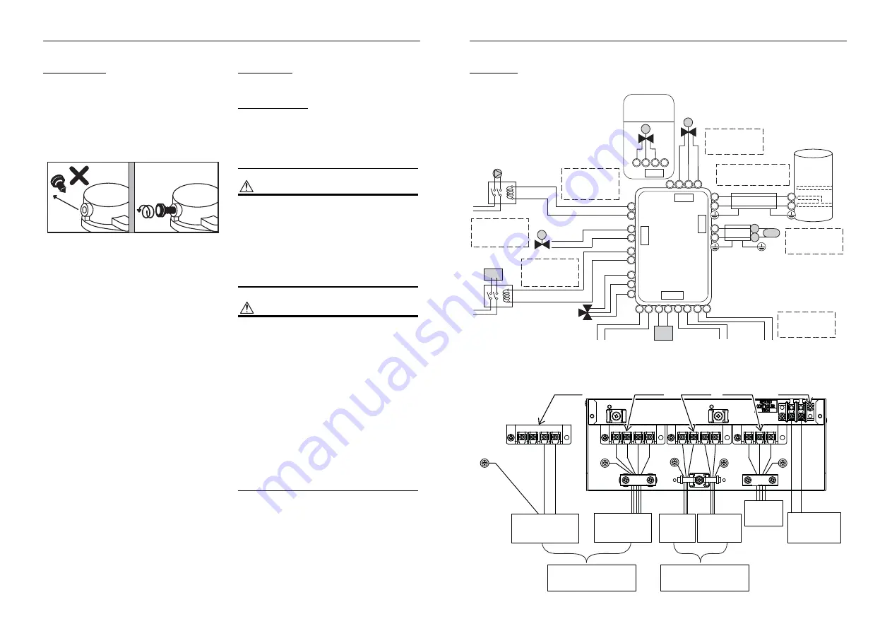
Control line
▼
Fig.7-17
▼
Fig.7-18
1
2
3
4
1
2
3
4
5
6
A
B
7 8 9 10
1 3 4 6 2 3 5 6
CN23
CN20
CN22
8
9
10
7 8 9 10
CN22
CN22
CW
CCW
N
Mixing-Valve
type 2 for 2 zone
control
Max 12 m
230 V 100 mA
0.75 mm² or more
Mixing-Valve type 1
for 2 zone control
Max 5 m shielded wire
0.75 mm² or more
Temp sensor in hot
water cylinder
Max 12 m
230 V 1 A
0.75 mm² or more
Pump (local)
Max 12 m
230 V 100 mA
0.75 mm² or more
Booster heater
(local)
Max 12 m
230 V 1 A
0.75 mm² or more
Alert output
(local)
Boiler operation
(local)
Defrost output
(local)
Compressor
operation output
(local)
Max 12 m non
voltage 0.75 mm² or
more
Temp sensor for
2 zone control
Max 5 m shielded
wire 0.75 mm² or
more
2Way-Valve for
cooling stop
3Way-Valve for hot
water cylinder
Input power
220-240V~50Hz
Input power
380-415V
3N~50Hz
Hot water
cylinder
Input power
220-240V~
50Hz
to Outdoor
Unit
to Second remote
controller
Backup heater power
supply
Hot water cylinder power
supply
TB03
TB03
TB02
TB01
TB04
21-EN
22-EN
Summary of Contents for HWT-1101XWHM3W-E
Page 39: ...2F30151001 1 ...


