background image

– 8 –

Hydro Unit

Installation Manual

„

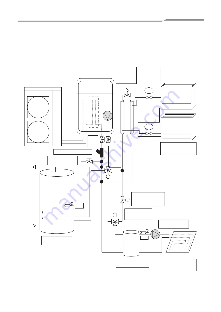
Example of 2-zone temperature control and hot water supply 
system

The following shows an example of the 2-zone temperature control.
A buffer tank and a water pump are required for the 2-zone temperature control.

Fig. 5-02

M

M

M

TTW

TFI

TRV

TRV

Temp. 

Regulating 

Valve 

(Mechanical)

Isolating 

Valves 

(Service)

Strainer (40 mesh / 0.4 mm)

Diverting 

3-Way 

Valve for 

Sanitary 

Hot 

Water 

Cylinder

Drain Cock for water 

Charge and Drain

Zone 1

Fan Coil Unit (Heating 

or Cooling)

Temperature 

Regulating 

Valve 

(Mechanical)

Hi-Pressure 

By-Pass 

Valve

Indirect Sanitary Hot 

Water Cylinder

Mixing 3-Way 

Valve for Under 

Floor Heating 

External Pump for 

Under Floor Heating

Motorized 2-Way Valve 

is required if fan coil 

units are in cooling 

operation.

Direct Buffer tank for 

Under Floor Heating

Zone 2

Under-floor Heating

(2-Way Valve Control)

8-EN

Summary of Contents for HFC series

Page 1: ...AIR TO WATER HEAT PUMP Hydro Unit Model name HWS P804XWHM3 E HWS P804XWHT6 E HWS P804XWHT9 E HWS P1104XWHM3 E HWS P1104XWHT6 E HWS P1104XWHT9 E English Installation Manual ...

Page 2: ...29 9 Test run 38 10 Maintenance 38 11 Sensor temperature monitoring function 39 12 Troubleshooting 40 Please read this Installation Manual carefully before installing the Air to Water Heat Pump This Manual describes the installation method of the hydro unit For installation of the outdoor unit follow the Installation Manual attached to the outdoor unit REFRIGERANT This Air to Water Heat Pump uses ...

Page 3: ... P804XWHT6 E 3N 6kW HWS P804XWHT9 E 3N 9kW HWS P1104XWHM3 E 3kW HWS P1104XWHT6 E 3N 6kW HWS P1104XWHT9 E 3N 9kW 220 230V model Outdoor unit HWS P804HR E HWS P1104HR E Power supply 220 230V 50Hz Type INVERTER Function Heating Cooling Heating Capacity kW 8 0 11 2 Input kW 1 68 2 30 COP W W 4 76 4 88 Cooling Capacity kW 6 0 10 0 Input kW 1 64 3 33 EER W W 3 66 3 00 Refrigerant R410A Dimension HxWxD m...

Page 4: ...9 E Back up heater capacity 3 0 6 0 9 0 Power supply for back up heater 220 230V 50Hz 380 400V 3N 50Hz 380 400V 3N 50Hz for hot water cylinder heater option 220 230V 50Hz Leaving water temperature Heating C 20 60 Cooling C 7 25 Hot water cylinder option HWS 1501CSHM3 E HWS 1501CSHM3 UK HWS 2101CSHM3 E HWS 2101CSHM3 UK HWS 3001CSHM3 E HWS 3001CSHM3 UK Water volume liter 150 210 300 Power supply 220...

Page 5: ...rescribed specification Heating Radiator s Fan coil s Under floor heating Heating Cooling all rooms Fan coil s Heating Cooling partly heating only Motorized 2 way valve for cooling Refer to Control parts specifications on page 20 Hot water supply Hot water cylinder Motorized 3 way valve Earth leakage breaker Refer to Control parts specifications on page 20 150 L HWS 1501CSHM3 E HWS 1501CSHM3 UK 21...

Page 6: ...ified installation professional to install maintain the Air to Water Heat Pump System Inappropriate installation may result in water leaks electric shock or fire Electrical work must be performed by a qualified electrician in accordance with the installation manual An inappropriate power supply capacity or installation may result in fire When completing any electrical works to the system ensure th...

Page 7: ...here is an external heating source such as a boiler When hot water over 60 C returns it may result in a failure of the unit or water leakage The flow rate of the circulating water must meet the following range 11 kW 18 L minute or more 8 kW 13 L minute or more If the flow rate becomes less than the minimum the protective device is activated to stop the operation To ensure the minimum flow rate of ...

Page 8: ... M M Fan Coil Units Cooling or Heating Isolating Ball Valves Strainer 40 mesh 0 4 mm Diverting 3 Way Valve for Sanitary Hot Water Cylinder Radiators Heating Only 2 Way Valve Control 2 Way Valve 2 Way Valve Alternative to Radiators Under floor Heating Heating Only 2 Way Valve Control Indirect Sanitary Hot Water Cylinder Drain Cock for water Charge and Drain Use the 2 way valve to isolate the heatin...

Page 9: ...ves Service Strainer 40 mesh 0 4 mm Diverting 3 Way Valve for Sanitary Hot Water Cylinder Drain Cock for water Charge and Drain Zone 1 Fan Coil Unit Heating or Cooling Temperature Regulating Valve Mechanical Hi Pressure By Pass Valve Indirect Sanitary Hot Water Cylinder Mixing 3 Way Valve for Under Floor Heating External Pump for Under Floor Heating Motorized 2 Way Valve is required if fan coil un...

Page 10: ...sor for refrigerant TC 7 Temperature sensor for water inlet TWI 8 Drain nipple 9 Water inlet connection 10 Refrigerant liquid connection 11 Air relief valve 12 Pressure relief valve 0 3 MPa 3 bar 13 Thermal protector auto 14 Temperature sensor for water outlet THO 15 Thermal protector Single operation 16 Water pump 17 Backup heater 3 kW 3 kW x 2 3 kW x 3 18 Manometer 19 Water outlet connection 20 ...

Page 11: ...t P C board MCC 1217 Option External output P C board MCC 1217 Option Relay P C board MCC 1431 MG SW RY04 MG SW RY02 External input P C board MCC 1214 Option Main P C board MCC 1511 Trans former Relay RY06 MG SW RY05 Relay RY01 Relay RY03 Fuse Fuse F9 F10 TB 07 TB07 10 EN ...

Page 12: ...heat Do not install the Hydro Unit to a movable object Do not install the Hydro Unit in a place exposed to vibration The unit must be installed in accordance with national wiring regulation The Hydro Unit must not be installed in a high humidity condition area Handling unpacking and checking the Hydro Unit The unit should be checked when it is delivered and any damage reported immediately to the c...

Page 13: ... system the service valve connection ports have also increased in size The use of R410A tools is required for correct installation of the system The use of the correct pipe sizes and wall thicknesses of copper pipe work is required for the correct installation of the system CAUTION Ensure all refrigerant pipes are protected from the invasion of dust and water Ensure all pipe work connections are t...

Page 14: ...unit to the Hydro Unit as shown below Fig 7 09 Align the flare connection on each pipe with the corresponding outlet connection on the Hydro Unit Tighten the flare nuts using fingers to secure the pipes in place Tighten the flare nuts using a torque wrench to the tightening torques shown below To prevent damage to the refrigerant pipes use two spanners to tighten the flare nut connections to the r...

Page 15: ...d at the water inlet of the Hydro Unit Install drain cocks locally procured for water charge and discharge at the lower part of the Hydro Unit Make the piping route a closed circuit An open water circuit may cause a failure Fig 7 11 Fig 7 12 H 7 m Hot water outlet connection 1 1 4 Water inlet connection 1 1 4 Attention To avoid water leak exchange the seal tapes to new one Attention Water used at ...

Page 16: ...total tank capacity Water expansion coefficient at each hot water temperature Vs Total water amount in the system P1 System pressure at tank setting position MPaabs water supply pressure 0 3 MPaabs recommended valve P2 Maximum pressure used during operation at tank setting position MPaabs safety valve setting pressure 0 4 MPaabs The absolute pressure value abs is obtained by adding the atmospheric...

Page 17: ...istics Minimum flow rate Head m Out of range Hydro unit QH Characteristics 220 230 V Pump duty 100 Pump duty 60 Pump duty 80 Flow rate L min 0 1 2 3 4 5 6 7 8 9 10 0 10 20 30 40 50 Head m Hydraulic heat exchanger 11 kW QH characteristics Minimum flow rate Hydro unit QH Characteristics 220 230 V Out of range Pump duty 100 Pump duty 60 Pump duty 80 Flow rate L min 16 EN ...

Page 18: ... electrical circuits are isolated before commencing the electrical installation The electrical installation must be completed by a qualified electrician The electrical installation must comply to all Local National and International electrical installation regulations This product must be earthed in accordance with Local National and International electrical installation regulations CAUTION The Hy...

Page 19: ...local Defrost output local Compressor operation output local Max 12 m non voltage 0 75 mm or more Temp sensor for 2 zone control Max 5 m shielded wire 0 75 mm or more 2Way Valve for cooling stop 3Way Valve for hot water cylinder Max 50 m shielded wire 0 50 mm or more 2nd remote controller 6B 6A 6D 6C TF1 TB 06 11 12 13 TB 01 Don t apply 220 240V or breakdown will occur TTW 31 32 L TB 03 HOT WATER ...

Page 20: ...re P804XWHM3 E 220 230V 50Hz 13 A 16 A 1 5 mm or more P804XWHT6 E 380 400V 3N 50Hz 13 A 13 A x 2P 16 A 1 5 mm or more P804XWHT9 E 380 400V 3N 50Hz 13 A 13 A x 3P 16 A 1 5 mm or more Power input for cylinder heater 220 230V 50Hz 12 A 16 A 1 5 mm or more TB03 Outdoor Hydro unit Connection 1 5 mm or more Hydro Cylinder Connection 1 5 mm or more TB03 Description Line spec Maximum current Maximum lengt...

Page 21: ...T or SPDT valves with drive times between 30 and 240 seconds can be used Valve drive time can be changed using function code 0C Description Output Maximum current Max voltage Maximum length External pump No 1 AC230V 1 A 12 m External boost heater AC230V 1 A 12 m Output as required when outdoor air temperature is 20 C or less Boiler control Non voltage contacts 0 5 A AC230 V 12 m Output as required...

Page 22: ...ted before commencing work The Outdoor Unit to Hydro Unit interconnecting cable must be sized in accordance with refer to Electrical supply cable specifications Connect the Outdoor Unit to Hydro Unit interconnecting cable as shown in the diagram above Ensure the Outdoor Unit to Hydro Unit interconnecting cable is secured using the cable clamp fitted in the electrical box Ensure the Outdoor Unit to...

Page 23: ...al regulations Connect the external booster heater to the Hydro Unit in accordance with the diagram shown below Connect the coil of the field supplied contactor to terminals 5 6 on Terminal Block 05 The contactor will energize in the event of low ambient conditions A separate dedicated electrical supply must be used for the external booster heater This must be connected through the contacts on the...

Page 24: ...heating Connect the 3 way diverter valve to terminals 7 8 and 9 on Terminal Block 05 Connect the 3 way diverter valve in accordance with the diagram below Fig 7 25 Fig 7 26 Fig 7 27 SW13 1 Type 1 2 wire spring return OFF Type 2 3 wire SPST OFF Type 3 3 wire SPDT ON 7 8 9 Type 1 SPRING RETURN port A to Hot water cylinder port AB to Hydro unit port B to Room heating or cooling port A open Hydro Unit...

Page 25: ...n the hot water cylinder requires a separate supply to Hydro Unit Connect the hot water cylinder heater electrical supply in accordance with shown below Live conductor Terminal L on Terminal Block 03 Neutral conductor Terminal N on Terminal Block 03 Earth Conductor Earth terminal on Terminal Block 03 Connect the hot water cylinder heater to the Hydro Unit as shown below Live conductor to hot water...

Page 26: ...onnection details Terminals 1 and 2 OPERATION on MCC 1217 TB Refer to Fig 7 32 Boiler Control Output L2 Boiler drive permission output Output enabled when outdoor ambient temperature 10 C Volt free contact specification shown below AC230 V 0 5 A maximum DC24 V 1 A maximum Connection details Terminals 3 and 4 EMG on MCC 1217 TB Refer to Fig 7 32 Fig 7 32 Defrost and Compressor operation Outputs Def...

Page 27: ...heating mode Output enabled when either heating or cooling mode selected on room thermostat locally supplied Volt free contacts Connection details Cooling Connection Terminals 3 COM and 2 COOL on MCC 1214TB Refer to Fig 7 34 Heating Connection Terminals 3 COM and 1 HEAT on MCC 1214TB Refer to Fig 7 34 Fig 7 34 Thermostat operation CAUTION Be sure to prepare a non voltage continuous contact for eac...

Page 28: ...to Water heat pump system The electrical safety checks should be completed by a qualified electrician All results measured should comply with your local national electrical installation regulations Earth continuity test On completion of the electrical installation a resistance test should be completed on the earth conductor to ensure continuity between all pieces of equipment on the earth conducto...

Page 29: ... of the Hydro unit to prevent miss wiring Do not apply AC 208 230V mains voltage to the remote controller as it will be damaged Remote controller wiring Connection diagram Second remote controller installation requirements Installation For a dual remote controller system install the remote controllers in the following way 1 Set one of remote controllers as the header remote controller Remote contr...

Page 30: ... 4 ON 1 2 3 4 ON 1 2 3 4 ON Fig 8 01 SW No DIP No Description Default After Commissioning Change 1 Change 2 Change 3 02 1 Boiler install location OFF Heating side after 3 way valve ON Before 3 way valve OFF 2 Not Used 3 Used to when an external cylinder thermostat is connected OFF No external cylinder thermostat ON External tank thermostat connected OFF 4 Used to when an external room thermostat i...

Page 31: ...one 1 Operation OFF Zone 1 activated ON Zone 1 de activated OFF 3 Used to activate Zone 2 Operation OFF Zone 2 de activated ON Zone activated OFF 4 Not Used 13 1 Used to determine type of 3 way diverting valve used on system OFF 2 wire spring return or SPST type valve ON SPDT type valve OFF 2 Used to activate external boiler output OFF external boiler output de activated ON external boiler output ...

Page 32: ...ons CODE No 01 to 91 3 Set data DATA with the TIME buttons 4 Press the SET button to determine the settings 5 The CL button is enabled only before the SET button is pressed and the function code is changed 6 Press the TEST button to end the settings Setting Remote controller Function Code 1 Press the TEST CL TEMP buttons for four seconds or more to enter the remote controller function code setting...

Page 33: ...Hot Water Heating Switching Temperature Heating operation takes precedence when the temperature lowers the set temperature Boiler HP Switching Temperature When the temperature lowers the set temperature the external boiler output is made 7 Setting Heating Auto Mode Temperature function code 27 to 31 A1 to A5 Compensate the target temperature when Auto is set for temperature setting on the remote c...

Page 34: ... Setting Heating Hot Water Switching when Boiler Is Used function code 3E When boiler is used make this setting to operate the Hydro Unit by the instruction from the boiler 16 Setting Heat Pump Operating Time for Hot Water Supply Operation Set the time period from the start of heat pump run to the start of heater energization at the beginning of hot water supply operation If a long period is set i...

Page 35: ...5 5 Anti Bacteria Setting Temperature C 0A 65 75 C 75 Start Cycle Day 0D 1 10 7 Start Time Hour 0C 0 23 22 Operation Time min 0B 0 60 30 6 Priority Mode Hot Water Heating Switching Temperature C 22 20 20 0 Boiler Heat Pump Switching Temperature C 23 20 20 10 7 Heating Auto Curve Settings Outside Temperature T0 C A1 30 20 C 20 Outside Temperature T1 C 29 15 0 C 10 Outside Temperature T2 C 0 0 Outsi...

Page 36: ... Time Specified Drive Time for Mixing Valve x10sec 0C 3 24 6 Mixing valve OFF control time mins 59 1 30 4 15 Boiler Heat Pump Synchronisation External Boiler Heat Pump Synchronisation 0 Synchronised 1 Not synchronised 3E 0 1 0 16 Maximum Operation Time Of Hot Water Heat Pump Maximum Heat Pump Operation Time In Hot Water Operation Priority Mode minutes 07 1 120 30 17 Cooling Operation 0 Cooloing He...

Page 37: ... Restart hot water and heating 1 Restart in the mode when stopping 2 Restart hot water 3 Restart heating 4 Tempo control 1 without heater 5 Tempo control 2 without HP and heater 61 0 5 0 Changing the control of S1 CN210 0 none 1 Hot water supply control In addition it is enabled only when switch 2_3 is set to OFF and FC61 is set to 3 B6 0 1 0 23 Hydro Unit Capacity Setting 0012 P804XWH 0015 P1104X...

Page 38: ...and 2 of the Hydro Unit To inhibit interlocking the water pump with the internal pump of the Hydro Unit set DIP SW10 3 on the Hydro Unit board to OFF Set DIP SW12 3 on the Hydro Unit board to ON Refer to page 29 Attach the temperature sensor TFI connected to terminals TB06 C and D of the Hydro Unit near the hot water inlet of the Hydro Unit Fix TFI sensor on the room heating supply pipe by using t...

Page 39: ...ting operation starts Check that the hydro unit starts heating Press the OPERATE MODE button and select cooling Cooling operation starts Check that the hydro unit starts cooling and that the floor heating system is not cooled Press the ZONE1 2 button to stop operation Press the HOT WATER button to start hot water supply operation Check that there is no air bite Check that hot water is present at t...

Page 40: ...TTW C 0B Mixing valve position step 0E Low pressure Ps 10kPa Outdoor unit data Item code Data name Unit 60 Heat exchange temperature TE C 61 Outside air temperature TO C 62 Discharge temperature TD C 63 Suction temperature TS C 65 Heat sink temperature THS C 6A Current A 6D Heat exchanger coil temperature TL C 70 Compressor operation Hz Hz 72 Number of revolutions of outdoor fan lower rpm 73 Numbe...

Page 41: ... way valve for hot water supply Check wiring and parts Hot water leaks from pressure relief valve Excessive hydraulic pressure Set hydraulic pressure considering pipe height and replenish water until manometer shows a value of set hydraulic pressure or more Insufficient capacity of expansion tank Check expansion tank capacity compared to total water amount If it is insufficient install another exp...

Page 42: ...A10 Antifreeze operation 2 1 Almost no or little water flow 2 Check the water inlet water outlet and heat exchange TWO TC sensors A11 Operation of the release protection Heating Cooling Hot water O 1 Almost no water flow 2 Defect of the flow switch 3 Check the water outlet temperature sensor TWO A12 Heating hot water heater error O O 1 Activated by a large load of heating or hot water supply 2 Che...

Page 43: ...ifications HWS P804xx E 0012 HWS P1104xx E 0015 L16 Setting error When ZONE1 has not been set while ZONE2 has been set 1 Check the body DP SW12_2 3 Check code Diagnostic functional operation Determination and action Operational cause Backup present Automatic reset F04 TD sensor error O 1 Check the resistance value and connection of the discharge sensor TD F06 TE sensor error O 1 Check the resistan...

Page 44: ... PC board MUCs error O 1 Replace the outdoor control board P03 The outlet temperature error O 1 Check the refrigeration cycle gas leak 2 Defect of the pulse motor valve 3 Check the resistance value of the discharge temperature sensor TD P04 The high pressure switch error O P05 The power supply voltage error O 1 Check the power supply voltage P07 Overheating of heat sink error O 1 Check the thread ...

Page 45: ...remote controller P22 Outdoor fan system error O 1 Check the lock status of the motor fan 2 Check the connection of the fan motor cable connector 3 Check the power supply voltage P26 Short circuit of the compressor driver element error O 1 Abnormality occurs when operating with the compressor wiring disconnected Check the control board 2 No abnormality occurs when operating with the compressor wir...

Page 46: ...reset Displayed when the abnormality is detected Defect in the reception of the remote controller 1 Check the remote controller crossover 2 Check the remote controller 3 Check the hydro power supply wiring 4 Check the water heat exchanger board E02 Defect in the signal transmission to the hydro unit Detected on the remote controller side Stop Automatic reset Displayed when the abnormality is detec...

Page 47: ...EF99808601 ...

Reviews: