Page 4
TABLE OF CONTENTS
SAFETY
.................................................................................................................................................. 1
INTRODUCTION
..................................................................................................................................... 6
GENERAL DESCRIPTION
...................................................................................................................... 7
Components .................................................................................................................................................... 7
Indicators Provided .......................................................................................................................................... 7
Figure 1 – Contactor Structure ........................................................................................................................ 7
RECEIVING, INSPECTION AND HANDLING
......................................................................................... 8
Receiving and Unpacking ................................................................................................................................ 8
Acceptance Inspection .................................................................................................................................... 8
Handling and Moving ....................................................................................................................................... 8
Figure 2 – Wear Gauge ................................................................................................................................... 8
INSTALLATION
...................................................................................................................................... 9
Ambient Conditions ......................................................................................................................................... 9
Mounting the Contactor ................................................................................................................................... 9
Main Circuit Cable Connections ...................................................................................................................... 9
Ground Connections ........................................................................................................................................ 10
Control Circuit Connections ............................................................................................................................. 10
Figure 3 – Control Voltage Selection for Closing Coils ................................................................................... 10
PRE-ENERGIZATION CHECK
................................................................................................................ 11
General ............................................................................................................................................................ 11
Electrical Checks ............................................................................................................................................. 11
OPERATION
........................................................................................................................................... 12
Figure 4 – Drive Unit Block Diagram ............................................................................................................... 12
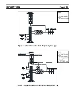
Figure 5 – Internal Connection of the Magnetically Held Type ....................................................................... 13
Figure 6 – Internal Connection of the Mechanically Latched Type ................................................................. 13
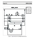
Figure 7 – Typical Control Circuit for Magnetically Held Type ........................................................................ 14
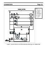
Figure 8 – Typical Control Circuit for Mechanically Latched Type 125VDC-250VDC Trip ............................. 15
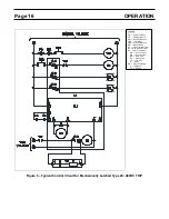
Figure 9 – Typical Control Circuit for Mechanically Latched Type 24VDC-48VDC Trip ................................. 16
MAINTENANCE
...................................................................................................................................... 17
Maintenance Program ..................................................................................................................................... 17
Maintenance Record ....................................................................................................................................... 17
Servicing Equipment ........................................................................................................................................ 17
Recommended Inspection and Maintenance Types ....................................................................................... 18
Table 1 – Tightening Torque ........................................................................................................................... 18
Table 2 – Check Points for Periodic Inspection ............................................................................................... 19
Table 3 – Gap/Wipe Standard Values (contactor in new condition) ................................................................ 20
Vacuum Check ................................................................................................................................................ 21
Figure 10 – Toshiba Portable Vacuum Checker ............................................................................................. 21
Figure 11 – Application of Test Voltage for Vacuum Check ............................................................................ 22
Electrical Service Life ...................................................................................................................................... 23
Mechanical Service Life ................................................................................................................................... 23
Figure 12 – Wipe Measurement ...................................................................................................................... 23
Service Life – Capacitor Switching .................................................................................................................. 23


