background image

Page 2

Accessories For T1 Modem Communications (with programming port):

PC Side

:

  a standard “straight-through” 9-25 pin RS-232 serial cable;

  a  

 9600 baud external modem.

PLC Side

:

  a standard “straight–through” 9-25 pin RS-232 serial cable;

  a “null-modem” adapter such as Radio Shack’s 9-9 pin Null Modem

  a Toshiba part number TKRS232T1 T1 programming cable

  a  

 9600 baud external modem.

See Note 2 on page 5

Now that we have discussed the basic hardware requirements, let’s look at the parameter settings
in T-PDS and the PLCs.  We will need to use the Computer Link connection when communicating
via modem, as the “Direct” connection will not work.  

T-PDS version 1.2

 is used in this application

note; see the last page for more details.  There are 3 Setup Steps:

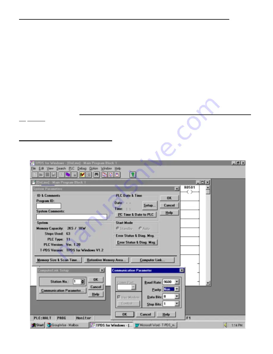
STEP 1:  CONFIGURE THE PLC

First, let’s set up the PLC’s Computer Link parameters.  Go 

Online

 with the T1 or T2E/T2N using

the normal “Direct” method.  We will need to open the System Parameters screen as shown below:

Summary of Contents for Eagle T1 Series PLCs

Page 1: ...pen circuit voltage with about 110Vac ring voltage This does not include the digital phone lines in most offices that use modern digital PBX systems Plugging a modem directly into one of these digital office lines may destroy the modem We used US Robotics 56K Sportster external modems for our tests but just about any external Hayes compatible modem will work Here is the list of equipment that you ...

Page 2: ...ee Note 2 on page 5 Now that we have discussed the basic hardware requirements let s look at the parameter settings in T PDS and the PLCs We will need to use the Computer Link connection when communicating via modem as the Direct connection will not work T PDS version 1 2 is used in this application note see the last page for more details There are 3 Setup Steps STEP 1 CONFIGURE THE PLC First let ...

Page 3: ...you have a T2E set the COM dip switch on the front of the module to the right hand position and then cycle power on the PLC This will set the T2E programming port up for no parity STEP 2 CONFIGURE T PDS Now that the PLC configuration is done we will now do the T PDS configuration on the PC We will need to go Offline and set the T PDS communication parameters as follows Go to the Options Communicat...

Page 4: ... Initialize parameter T PDS will not successfully dial out or disconnect without this The parameter shown here is the S25 register which controls the time that the PC modem can have a DTR loss before hanging up Since T PDS toggles the DTR line on the COM port during modem connection and hang up this parameter must be set to accommodate your modem The setting of S25 50 worked on the US Robotics mod...

Page 5: ...to dial out If T PDS hangs up as soon as the modems establish carrier or will not hang up when you go OFFLINE then adjust your DTR timeout parameter S25 on USR modem If you are using a T1 remember to attach the null modem module to the modem s RS 232 cable Also in the T1 version 1 2 as well as the Super T1 40 register SW038 is the Computer Link Response Delay setting which can be used with the def...

Page 6: ... A NO PARITY SETTING If you have one of these PLCs and would like to use modem communications you must use a modem that supports odd parity This will apply if you have a T1 with firmware version earlier than 1 2 or any of the T2 series that is not a T2E T2N Most T3 s will also require an odd parity modem One source for these modems is TELENETICS ph 714 455 4000 fax 714 455 4010 Telenetics model nu...

Reviews: