background image

Remote controller with weekly timer

Owner’s Manual

– 8 –

3

SETTING THE CURRENT DAY OF THE WEEK 

AND CLOCK TIME

• Set the current clock time and day of the 

week.

• The day of the week and clock settings 

can be performed whether the air 
conditioner is running or shut down.
* The air conditioner continues to operate 

(run) while the day of the week and 

clock settings are being performed.

• The normal operation of the air conditioner 

or a program for a scheduled operation 
can be input even without performing the 
day of the week and clock settings, but the 
scheduled operation cannot be executed. 
In order to execute scheduled operations, 
the day of the week and clock must be set 
without fail.

• Before this remote controller is shipped 

from the factory, the initial setting (default) 
of the 24-hour display is established for 
the clock time display, but this can be 
changed to the 12-hour (AM/PM) display.
* If you want to use the 12-hour time 

display, refer to the “Selecting the 

remote controller functions” section.

* In these instructions, the 24-hour 

display is used in the figure and 

descriptions.

Preparations

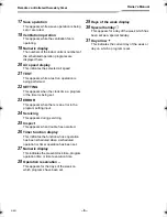
Turn on the ground fault interrupter.

• When the power is turned on, a dividing 

line appears on the remote controller 
display.
* For about a minute after the power has 

been turned on, 

 on the LCD 

screen blinks, and there will be no 

response to the keys of the remote 

controller even when they are pushed.

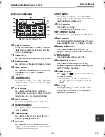
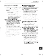
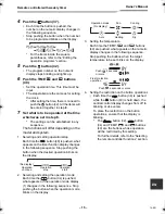
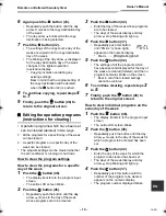
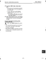
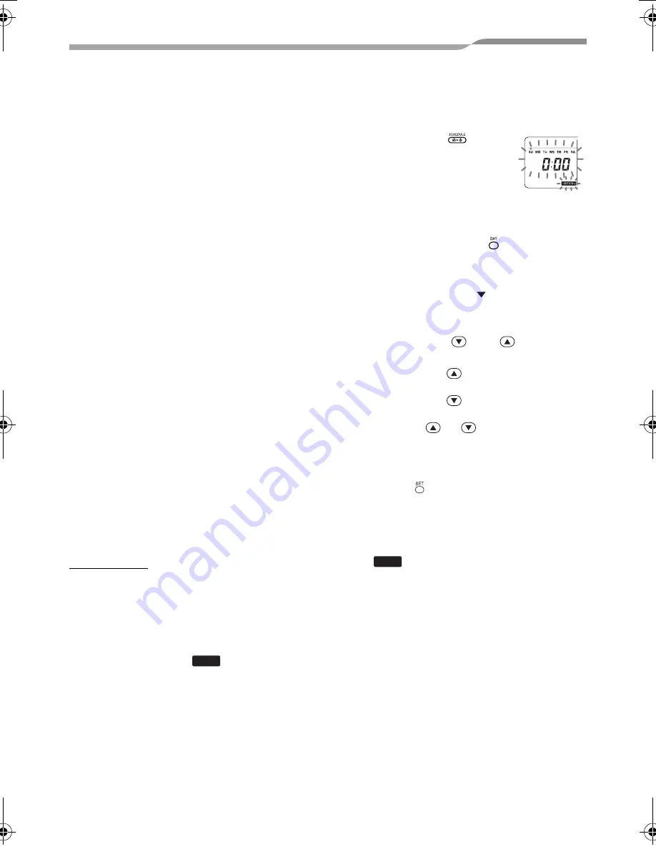
1

Hold down the 

 button 

(48) for at least 4 
seconds.

• The display transfers to the 

day of the week/clock 
setting screen.

• The whole LCD display blinks.

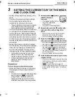
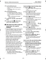
2

Repeatedly push the   button (45), 
and select the current day of the 
week.

• Move the day arrow   to the position 

above the current day of the week.

• The LCD display continues to blink.

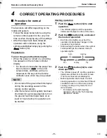
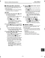
3

Push the TIME 

 and 

 buttons 

(40), and select the current clock time.

• Each time the 

 button (40) is pushed, 

the clock is moved forward by one minute.

• Each time the 

 button (40) is pushed, 

the clock is moved back by one minute.

• When the 


or 

 button is held down, 

the clock is moved forward or back in 10-
minute increments.

• The LCD display continues to blink.

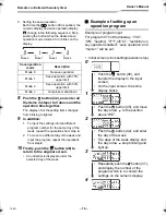
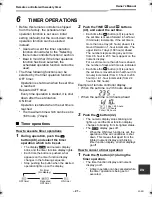
4

Push the   button (42) to return to the 
original screen.

• As soon as the button is pushed, the clock 

starts running. (Do this in synchronization 
with a time signal.)

on the LCD screen goes off.

• After the clock has been set, the entire LCD 

screen lights, but the colon (“:”) continues 
to blink.

SETTING

<Blinks>

SETTING

7-EN

+00EH99677901_01EN_OM_Remo_Weekly_UL.book  Page 8  Thursday, October 8, 2009  2:03 PM

Summary of Contents for Carrier RBC-AMS41UL

Page 1: ...ER FOR AIR CONDITIONER SPLIT TYPE Owner s Manual Owner s Manual Remote controller 2 English Manuel du proprietaire Télécommande 26 Français Remote Controller Model name Remote controller with weekly timer RBC AMS41UL ...

Page 2: ... 1 SAFETY PRECAUTIONS 3 2 PARTS AND THEIR FUNCTIONS 5 3 SETTING THE CURRENT DAY OF THE WEEK AND CLOCK TIME 8 4 CORRECT OPERATING PROCEDURES 9 5 SCHEDULED OPERATIONS 14 6 TIMER OPERATIONS 21 7 TROUBLESHOOTING 22 8 SELECTING THE REMOTE CONTROLLER FUNCTIONS 24 1 EN ...

Page 3: ...ks and or a fire may result if you attempt to install the air conditioner yourself and the air conditioner ends up not being installed perfectly Use only with the authorized air conditioner units Be absolutely sure to use only the authorized air conditioner units designated by the manufacturer Also ask a contractor with specialized experience to install them Electric shocks and or a fire may resul...

Page 4: ...electric shocks a fire and or trouble Consult your dealer CAUTION Do not drop the product or subject it to strong impact Failure to heed this caution may cause malfunctioning Use only the fuses with the correct amperage Use of pieces of wire including copper wiring may cause a fire and or trouble Relocation and repair precautions WARNING Do not undertake any repair work yourself Under no circumsta...

Page 5: ...is displayed This appears before a heating operation starts or while defrosting 10 No function This appears when a button is pushed but there is no corresponding function 11 FROST PROTECT operation This appears during a frost protection operation 12 Numeric display This displays the numeric value of the temperature the numerical order of the trouble history events or the code numbers when the func...

Page 6: ...t 23 ERROR This appears when there is an error in the program setting input 24 Servicing This appears during servicing 25 Inspect This appears when trouble has occurred 26 Timer function display This indicates the function whose operation has been scheduled when a scheduled operation or timer operation has been set 27 Numeric display This indicates the present clock time program operation time or ...

Page 7: ...me is set 41 CL button Use this when clearing the setting of the program for a scheduled operation or timer operation which is being set 42 SET button Use this when entering the settings of the program for a scheduled operation or timer operation which is being set 43 TEST button Use this for servicing This button is not normally used 44 FLT RESET button Use this to reset extinguish the filter dis...

Page 8: ...Preparations Turn on the ground fault interrupter When the power is turned on a dividing line appears on the remote controller display For about a minute after the power has been turned on on the LCD screen blinks and there will be no response to the keys of the remote controller even when they are pushed 1 Hold down the button 48 for at least 4 seconds The display transfers to the day of the week...

Page 9: ...ontrol system After the remote control system has been shut down for a prolonged period turn on the ground fault interrupter back on at least 12 hours before its operation is to be started Starting operation 1 Push the button 32 to start operation The ON lamp lights and the operation details are displayed on the LCD screen 2 Push the button 34 and select the mode of operation Each time this button...

Page 10: ...s cold and to rise toward the ceiling where it collects when it is warm CAUTION For cooling operations set the louvers to the horizontal blow out position Performing cooling operations with the louvers at the downward blow out position may cause condensation to form around the air outlets and louver surfaces and water may drip For further details refer to the operating instructions of the air cond...

Page 11: ...to all the indoor units Frost protection operation heating at 46 F 8 C The functions will differ depending on the model and system This is a heating operation function which is specially designed for use in cold regions where it will keep the indoor temperature constant while you are out To enable this function an application control setting is required Consult your dealer or a contractor with spe...

Page 12: ...on moves into action to dry out the insides of the indoor units using the fan operation so as to keep the indoor units clean For further details refer to the operating instructions of the air conditioner 1 The self cleaning operation starts automatically when the air conditioner was in the auto cooling dry or cooling mode for at least 10 minutes before its operation is shut down The ON lamp goes o...

Page 13: ...bstacle while it is going down it stops Several seconds after the up down grille rises and is neatly stowed in the air intake the motor stops The louver swings while the grille is going up or down When the grille is stowed in the panel this stowing operation is repeated 3 times to ensure that the grille is safely stowed away 4 Push the button 32 to stop the up down grille The up or down movement o...

Page 14: ...ctor with specialized experience Concerning the Continue xx setting The Continue setting can be established for the operation ON OFF operation mode and temperature setting items This setting causes the current operation modes of the indoor units to be continued Continue is set on the initial screen for each item of each program number so in the example of the operation given above there is no need...

Page 15: ...equence Stop pushing the button when the desired operation blinks on the display 2 Selecting and setting the operation mode Each time the button 34 is pushed what appears on the operation mode display 1 changes in the following sequence Stop pushing the button when the operation mode blinks on the display 3 Setting the temperature Each time the TEMP and buttons 49 are pushed what appears on the nu...

Page 16: ...al screen An underbar is displayed under the selected day of the week Example of setting up an operation program Example of program input For program 01 for Wednesday 7 00 ON heating 77 F 25 C restriction on key operation enabled save operation and mode 1 will be set Initial screen clock setting operation stop Save operation mode Description Mode 0 No save operation Mode 1 Save operation with 75 u...

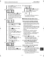
Page 17: ...the button 41 within 5 seconds of completing step 1 The symbol on the timer function display stops blinking and goes off Push the button 42 and enter the program number The numeric display stops blinking and lights up 5 Push the TIME and buttons 40 and set the operation time If the buttons are held down for four or more seconds the time can be moved forward or back in 10 minute increments 6 1 Sele...

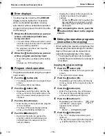
Page 18: ...button 37 Each time this button is pushed the program number and editing type are scrolled forward in sequence on the numeric display Display the number of the program to be checked and check the program s settings Unless the button 42 is pushed the key operations are canceled in which case the program settings will remain unchanged 5 After completing the check push the button 46 to return to the ...

Page 19: ...rs to the program input screen The entire LCD screen blinks 2 Push the button 45 Repeatedly push the button until the day arrow moves to the day of the week whose programs are to be cleared 3 Push the button 42 Enter the day of the week whose programs are to be cleared The days of the week display and day arrow stop blinking and light up 4 Push the button 37 Repeatedly push this button until PG CL...

Page 20: ...as no program settings The special holiday setting can be established whether the air conditioner is running or shut down How to establish the special holiday setting 1 Push the button 46 The display transfers to the program input screen The entire LCD screen blinks 2 Push the button 45 Repeatedly push the button until the day arrow moves to the day of the week which is to be set as a special holi...

Page 21: ...the TIME and buttons 40 and select the set time Each time the button 40 is pushed the set time is moved forward in half hour 30 minute increments If the set time is more than one day 24 hours ahead it is moved forward in 1 hour increments The upper limit is 7 days 168 hours ahead The numbers representing any set time from 0 5 hour to 23 5 hours appear on the numeric display For a set time more tha...

Page 22: ... off and give the model number and details of the symptoms to your dealer Do NOT attempt to remedy the problem yourself due to the dangers involved Trouble diagnosis Checks and inspections When trouble has occurred in the air conditioner an inspection code and the number of the indoor unit concerned blink on the numeric display Inspection codes are displayed only during operation If the display ha...

Page 23: ...t event Do not push the button 41 since all the trouble history events of the indoor units will be deleted 3 After checking the events push the button 43 to return to the original screen Concerning trouble occurring in the remote controller and blink at the same time This means that trouble has occurred on the remote controller s circuit board Contact your dealer Normal air conditioner operations ...

Page 24: ...iginal screen When the button 42 is pushed the numeric displays and display stop blinking and light up and when the button 43 is pushed again they go off Items to be set 24 hour 12 hour display setting code No 10 The 24 hour display or 12 hour AM PM display can be selected for the clock which is displayed on the remote controller This item s selection is also reflected on the clock displayed on th...

Page 25: ...ontroller The following functions can be selected using the DIP switches on the remote controller s circuit board Setting procedure Open the back cover of the remote controller and select the functions using the DIP switches located at the bottom left of the circuit board After establishing the settings turn the ground fault interrupter off and then back on Setting items Remote controller header f...

Page 26: ...EH99677901 ...
Reviews: