background image

2. MAJOR UNIT REPLACEMENT 

EO18-33023 

(Revision Date: Dec. 16, 2008) 

2.9 Replacing the Cover Open Switch and Media Sensor (Lower) 

2-18 

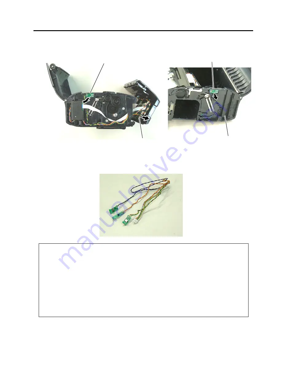
5)  Remove the Cover Open Switch (L) and Cover Open Switch (R) from the Base Cover. 


6)  Replace the Media Sensor (Lower) and Cover Open Switches (L) and (R) with a new one, then reassemble 

in the reverse order of removal. 


Cover Open Switch (L)

Cover Open Switch (R)

Connector 

Base Cover

NOTES: 

1.  After replacing the Media Sensor, refer to the Setting Operation Manual or System Mode Manual and

perform the following operations. 
1. Perform a RAM clear. 
2. Perform the sensor adjustment. 

2.  After replacing the Media Sensor, perform an operation check for the cover open switch as follows. 
 

When the top cover is fully opened, make sure “Cover Open” is displayed on the LCD. 


When either side of the top cover is opened, make sure “Cover Open” is displayed on the LCD. 


When the top cover is fully closed, make sure the print operation is performed correctly. 

  If the cover open switch does not operate correctly, this may result from the wrong connection of the

sensor connector, poor contact of the cable, etc.  Make sure the sensor connector is surely connected
to CN402 on the CPU PC board and the cable is not broken. 

Summary of Contents for B-EP4DL Series

Page 1: ...PRINTED IN JAPAN TOSHIBA Potable Printer B EP4DL SERIES Document No EO18 33023 Original Sep 2008 Revised Maintenance Manual ...

Page 2: ...ctions Failure to do so could create safety hazards such as fire or electrocution NOTE Failure to follow manual instructions or any unauthorized modification substitution orchange to this product will void the limited product warranty ...

Page 3: ...e 1 UNPACKING 1 1 1 1 Procedure 1 1 1 2 Checks 1 1 2 MAJOR UNIT REPLACEMENT 2 1 2 1 Replacing the CPU PC Board 2 1 2 2 Replacing the LCD Unit 2 8 2 3 Replacing the Peel off Roller 2 9 2 4 Replacing the Peel off Sensor 2 10 2 5 Replacing the Drive PC Board 2 12 2 6 Replacing the Battery Terminal 2 13 2 7 Replacing the Stepping Motor 2 14 2 8 Replacing the Print Head 2 15 2 9 Replacing the Cover Ope...

Page 4: ...dure 1 Open the carton 2 Unpack the accessories from the carton 3 Unpack the printer NOTE Keep the carton and pad for future transportation of the printer 1 2 Checks 1 Check for damage or scratches on the machine 2 Confirm that none of the accessories are missing ...

Page 5: ... leaking lithium ion battery 5 Before handling the main parts be sure to discharge static electricity in human body through other metals Failure to do this may damage the CPU PC board print head etc NOTES 1 Before replacing the main parts print out the maintenance counter values and the parameter values and keep the printout Refer to Section 4 2 Diagnostics Test in the System Mode Manual After rep...

Page 6: ...t Side Cover in the direction of the arrow 6 Remove the Right Side Cover and the Front Cover in the direction of the arrow respectively NOTE The Gears shown in the picture below are not secured and are easily removed Be careful not to drop and break or lose them Top Cover Top Cover Open Button Left Side Cover Gear Right Side Cover Front Cover ...

Page 7: ...nt Cover 6 Disconnect all Connectors and FPC Cable from the CPU PC Board NOTE Before disconnecting the FPC Cable release the Connector Lock 7 Disconnect the Earth Terminal from the Drive PC Board Front Cover CPU PC Board FPC Cable Connector Lock CPU PC Board Drive PC Board Earth Terminal ...

Page 8: ...ard 2 4 8 Open the Hooks then remove the CPU PC Board from the Front Cover 9 Remove the screw then remove the Earth Terminal 10 Replace the CPU PC Board with a new one then reassemble in the reverse order of removal Hook Hook CPU PC Board T 2x5 Screw Earth Terminal ...

Page 9: ...slots of the printer enclosure Fit the tabs A to D into the slots A to D Front Cover Tab Tab B Tab C Tab D A B C D NOTES 1 Make sure that the pins on the both sides of the front cover are fit in position as shown in the pictures below 2 Do not reassemble the Front Cover while the Top Cover Open Button is pressed Doing so may cause the Top Cover not to open Pin Top Cover Open Button Good No Good ...

Page 10: ...into the slots A to C NOTE It is easy to mount the left side cover if you fit the tabs from the LCD side in order then secure the bottom side Be careful not to catch the cable by the cover while reassembling Tab A Tab B Tab C A B C NOTE It is easy to mount the right side cover if you fit the tabs from the LCD side in order then secure the bottom side Be careful not to catch the cable by the cover ...

Page 11: ...rform an LED check in the system mode and make sure the LED lights properly If the LED does not light properly this may result from the disconnection of the harness from the CPU PC board the unset battery or the run down battery etc Make sure the connection of the cables and the battery status When they are correct the LED failure may result from the initial failure of the CPU PC board and replace...

Page 12: ... in the system mode and make sure none of dots are missing Regarding the procedures for the LCD check refer to Section 4 2 4 in the System Mode Manual If the LCD does not display clearly refer to Section 4 4 2 in the System Mode Manual and perform an LCD density setting When the LCD dots are missing make sure the LCD cable is surely connected to the CPU PC board If the connection of the cable is c...

Page 13: ...ewdriver then remove the Peel off Roller Ass y 3 Remove the two Peel off Rollers and the two Roller Clips from the Roller Shaft 4 Replace the Peel off Roller with a new one then reassemble in the reverse order of removal Roller Clip Straight Slot Screwdriver Peel off Roller Roller Clip Peel off Roller Roller Shaft NOTE Be careful of the orientation of the Roller Clips as shown in the picture below...

Page 14: ...efer to Section 2 1 Replacing the CPU PC Board 2 Disconnect the Connector from the CPU PC Board 3 Pull out the Cover Shaft then remove the Peel off Sensor Unit 4 Release the Peel off Sensor Cover from the Hooks 5 Remove the Peel off Sensor Cover Shaft Hook Peel off Sensor Unit Hook Peel off Sensor Cover Peel off Sensor Peel Off Sensor Unit Connector CPU PC Board ...

Page 15: ...moval NOTES 1 Be careful of the orientation of the Peel off Springs as shown in the picture below when reassembling the Peel off Sensor Unit 2 After replacing the Peel off Sensor refer to the Setting Operation Manual or System Mode Manual and perform the following operations zPerform the sensor adjustment Peel off Spring L Peel off Spring R Peel off Sensor Unit ...

Page 16: ...n 2 1 Replacing the CPU PC Board 2 Disconnect all Connectors and FPC Cable from the Drive PC Board 3 Remove the Drive PC Board from the Guide 5 Replace the Drive PC Board with a new one then reassemble in the reverse order of removal Drive PC Board Drive PC Board Guide NOTE Before disconnecting the FPC Cable release the Connector Lock Connector Lock FPC Cable Drive PC Board ...

Page 17: ...over Left Cover and Front Cover Refer to Section 2 1 Replacing the CPU PC Board 2 Remove the Drive PC Board Refer to Section 2 5 Replacing the Drive PC Board 3 Hold down the Hook and remove the Battery Terminal upward 4 Replace the Battery Terminal with a new one then reassemble in the reverse order of removal Hook Battery Terminal ...

Page 18: ...eft Cover and Front Cover Refer to Section 2 1 Replacing the CPU PC Board 2 Remove the two screws 3 Disconnect the Connector from the Drive PC Board 4 Remove the Stepping Motor Replace the Stepping Motor with a new one then reassemble in the reverse order of removal Stepping Motor SMW 3x8 Screw Stepping Motor Drive PC Board Connector ...

Page 19: ... E Rings NOTE Carefully remove the E Rings in order not to damage the Print Head Element 4 Remove the right and left Shafts Media Sensor Holder E Ring Print Head Shaft E Ring Shaft CAUTION 1 Before handling the print head be sure to discharge static electricity in human body through other metals Failure to do this may damage the print head element 2 Never touch the print head element directly by h...

Page 20: ...tor Head FPC NOTES 1 After replacing the Print Head refer to the Setting Operation Manual or System Mode Manual and perform the following operations zPerform a RAM clear 2 After replacing the Print Head perform the print head broken element check and make sure none of the elements are broken Refer to Section 4 2 2 in the System Mode Manual Also perform a test print and make sure the print quality ...

Page 21: ... Right Cover Left Cover and Front Cover Refer to Section 2 1 Replacing the CPU PC Board 2 Release the Hooks by pulling the Paper Guides then remove the Paper Guide Ass y 3 Remove the Media Sensor Holder and Print Head Refer to Section 2 8 Replacing the Print Head 4 Remove the Media Sensor Lower from the Media Sensor Holder Hook Paper Guide Media Sensor Lower Media Sensor Holder Paper Guide Ass y ...

Page 22: ...perform the following operations 1 Perform a RAM clear 2 Perform the sensor adjustment 2 After replacing the Media Sensor perform an operation check for the cover open switch as follows When the top cover is fully opened make sure Cover Open is displayed on the LCD When either side of the top cover is opened make sure Cover Open is displayed on the LCD When the top cover is fully closed make sure ...

Page 23: ... and Front Cover Refer to Section 2 1 Replacing the CPU PC Board 2 Remove the two screws which secure the Outlet Paper Guide Ass y 3 Release the Hooks then remove the Outlet Paper Guide Ass y 4 Remove the Media Sensor Upper 5 Disconnect the cables from the Main PC Board Hook Outlet Paper Guide Ass y Screw Hook Media Sensor Upper Main PC Board Connector ...

Page 24: ...Replace the Media Sensor Upper with a new one then reassemble in the reverse order of removal NOTE After replacing the Media Sensor refer to the Setting Operation Manual or System Mode Manual and perform the following operations 1 Perform a RAM clear 2 Perform the sensor adjustment ...

Page 25: ...en Ass y 3 Replace the Platen Ass y with a new one then reassemble in the reverse order of removal Hook Platen Ass y Hook NOTES 1 After replacing the Platen refer to the Setting Operation Manual or System Mode Manual and perform the following operations zPerform a RAM clear 2 Perform a test print and make sure printing is even Refer to Section 4 6 in the System Mode Manual If the printing is uneve...

Page 26: ...dia cover completely 3 Remove the jammed media and re load the media roll correctly 4 Replace the print head FPC harness or the print head ass y 5 Open the media cover and allow the print head to cool 6 Open the media cover and close it again Replace the CPU PC board ass y 7 Open the media cover and close it again Erase the data 8 Open the media cover and close it again Send the correct print mode...

Page 27: ...3 Connect the interface PC board ass y with the CPU PC board ass y completely 4 Replace the FPC cable for the interface PC board Poor print quality 1 The print head is dirty 2 Unspecified media is used 1 Clean the print head 2 Change the media to the specified one The print start position is not detected 1 The sensor is not adjusted properly 2 The sensor is not installed properly 3 The sensor or t...

Reviews: