background image

User's Manual

T

HE

 G

RAND

 T

OUR

2-16

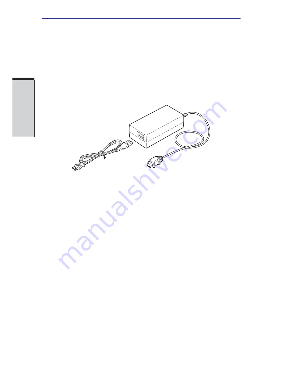
AC adaptor

The AC adaptor converts AC power to DC power and reduces the voltage supplied
to the computer. It can automatically adjust to any voltage from 100 to 240 volts and
to a frequency of either 50 or 60 hertz, enabling you to use the computer in almost
any country/region.

To recharge the battery, simply connect the AC adaptor to a power source and the
computer. See Chapter 6,


Power and Power-Up Modes

 for details.

Figure 2-11  The AC adaptor

CAUTION: 

Use only the AC adaptor that came with the computer or an

equivalent optional adaptor. Use of the wrong adaptor could damage
your computer. TOSHIBA assumes no liability for any damage in such
case.

WARNING: 

Use only the AC adaptor supplied as an accessory. Other

AC adaptors have different voltage and terminal polarities and use of
them may produce heat and smoke or even result in fine or rupture.

Summary of Contents for A40 Series

Page 1: ...TOSHIBA Satellite A40 Series Portable Personal Computer User s Manual ...

Page 2: ...n However succeeding computers and manuals are subject to change without notice TOSHIBA assumes no liability for damages incurred directly or indirectly from errors omissions or discrepancies between the computer and the manual Trademarks Intel Intel Speed Step Pentium and Celeron are trademarks or registered trademarks of Intel Corporation or its subsidiaries in the United States and other countr...

Page 3: ... is encouraged to try to correct the interference by one or more of the following measures Reorient or relocate the receiving antenna Increase the separation between the equipment and receiver Connect the equipment into an outlet on a circuit different from that to which the receiver is connected Consult the dealer or an experienced radio TV technician for help WARNING Only peripherals complying w...

Page 4: ...Inc 9740IrvineBoulevard Irvine California92618 1697 Telephone 949 583 3000 EUDeclarationofConformity TOSHIBA declares that the product PSA40 conforms to the following Standards SupplementaryInformation The product complies with the requirements of the LowVoltageDirective73 23 EEC theEMCDirective 89 336 EECand ortheR TTEDirective1999 05 EEC This product is carrying the CE Mark in accordance with th...

Page 5: ...he following networks It has been tested to and found to conform with the additional require mentsconditionalinEG201121 Germany ATAABAN005 AN006 AN007 AN009 AN010and DE03 04 05 08 09 12 14 17 Greece ATAABAN005 AN006andGR01 02 03 04 Portugal ATAABAN001 005 006 007 011andP03 04 08 10 Spain ATAABAN005 007 012 andES01 Switzerland ATAABAN002 All other countries regions ATAABAN003 004 Specific switch se...

Page 6: ...s must be made within a total of three minutes The internal modem is approved by Japan Approvals Institute for Telecommunica tionsEquipment A02 0604JP Pursuant to FCC CFR 47 Part 68 When you are ready to install or use the modem call your local telephone company andgivethemthefollowinginformation The telephone number of the line to which you will connect the modem The registration number that is l...

Page 7: ...e you notice in writing to allow you to make any changes necessary to maintain uninterrupted service If problems arise If any of your telephone equipment is not operating properly you should immedi ately remove it from your telephone line as it may cause harm to the telephone network If the telephone company notes a problem they may temporarily discon tinue service When practical they will notify ...

Page 8: ...ing this equipment users should ensure that it is permissible to be connected to the facilities of the local telecommunications company The equipment must also be installed using an acceptable method of connection The customer should be aware that compliance with the above conditions may not prevent degradation of service in some situations Repairs to certified equipment should be coordinated by a...

Page 9: ... a valid Austel permit This modem has been designed to specifically configure to ensure compli ance with Austel standards when the country region selection is set to Australia The use of other country region setting while the modem is attached to the Australian PSTN would result in you modem being operated in a non compliant manner To verify that the country region is correctly set enter the comma...

Page 10: ...er Telecom customers SomeparametersrequiredforcompliancewithTelecom sPTCSpecifications are dependent on the equipment PC associated with this modem The associated equipment shall be set to operate within the following limits for compliancewithTelecomSpecifications a There shall be no more than 10 call attempts to the same number within any 30 minute period for any single manual call initiation and...

Page 11: ...ialing standard Numbertobedialed 0123456789 Numbertoprogramintocomputer 0987654321 Note that where DTMF dialing is used the numbers should be entered normally The transmit level from this device is set at a fixed level and because of this there may be circumstances where the performance is less than optimal Before reporting such occurrences as faults please check the line with a standard Telepermi...

Page 12: ... of Telepermit labels subject to the general instructions on format size and colour on the attached sheet The Telepermit label must be displayed on the product at all times as proof to purchasers and service personnel that the product is able to be legitimately connected to the Telecom network The Telepermit label may also be shown on the packaging of the product and in the salesliterature asrequi...

Page 13: ...he unit ever require maintenance contact an authorized service location 2 Use of controls adjustments or the performance of procedures other than those specified may result in hazardous radiation exposure 3 To prevent direct exposure to the laser beam do not try to open the enclosure Location of the required label CERTIFICATION THIS PRODUCT COMPLIES WITH DHHS RULES 21 CFR CHAPTER 1 SUBCHAPTER JAPP...

Page 14: ... location 2 Use of controls adjustments or the performance of procedures other than those specified may result in hazardous radiation exposure 3 To prevent direct exposure to the laser beam do not try to open the enclosure Location of the required label CERTIFICATION THIS PRODUCT COMPLIES WITH DHHS RULES 21 CFR CHAPTER 1 SUBCHAPTER JAPPLICABLE ATDATEOFMANUFACTURE CLASS 1 LASER PRODUCT LASER KLASSE...

Page 15: ...e location 2 Use of controls adjustments or the performance of procedures other than those specified may result in hazardous radiation exposure 3 To prevent direct exposure to the laser beam do not try to open the enclosure PRODUCT IS CERTIFIED BY THE MANUFACTURER TO COMPLY WITH DHHS RULES 21 CFR SUBCHAPTER J APPLICABLE AT THE DATE OF MANUFACTURE MANUFACTURED TOSHIBA CORPORATION 1 1 SHIBAURA 1 CHO...

Page 16: ...ocation 2 Use of controls adjustments or the performance of procedures other than those specified may result in hazardous radiation exposure 3 To prevent direct exposure to the laser beam do not try to open the enclosure PRODUCT IS CERTIFIED BY THE MANUFACTURER TO COMPLY WITH DHHS RULES 21 CFR SUBCHAPTER J APPLICABLE AT THE DATE OF MANUFACTURE MANUFACTURED TOSHIBA CORPORATION 1 1 SHIBAURA 1 CHOME ...

Page 17: ...location 2 Use of controls adjustments or the performance of procedures other than those specified may result in hazardous radiation exposure 3 To prevent direct exposure to the laser beam do not try to open the enclosure PRODUCT IS CERTIFIED BY THE MANUFACTURER TO COMPLY WITH DHHS RULES 21 CFR SUBCHAPTER J APPLICABLE AT THE DATE OF MANUFACTURE MANUFACTURED TOSHIBA CORPORATION 1 1 SHIBAURA 1 CHOME...

Page 18: ...e location 2 Use of controls adjustments or the performance of procedures other than those specified may result in hazardous radiation exposure 3 To prevent direct exposure to the laser beam do not try to open the enclosure PRODUCT IS CERTIFIED BY THE MANUFACTURER TO COMPLY WITH DHHS RULES 21 CFR SUBCHAPTER J APPLICABLE AT THE DATE OF MANUFACTURE MANUFACTURED TOSHIBA CORPORATION 1 1 SHIBAURA 1 CHO...

Page 19: ...service location 2 Use of controls adjustments or the performance of procedures other than those specified may result in hazardous radiation exposure 3 To prevent direct exposure to the laser beam do not try to open the enclosure THIS PRODUCT COMPLIES WITH DHHS RULES 21 CFR SUBCHAPTER J APPLICABLE AT DATE OF MANU FACTURE MANUFACTURED Hitachi LG Data Storage Inc 26 5 TORANOMON 1 CHOME MINATO KU TOK...

Page 20: ...e of controls adjustments or the performance of procedures other than those specified may result in hazardous radiation exposure 3 To prevent direct exposure to the laser beam do not try to open the enclosure MFD SER NO CERTIFICATION THIS PRODUCT COMPLIES WITH 21 CFR 1040 10 AND 1040 11 EXCEPT FOR DEVIATIONS PURSUANTTO LASER NOTICE NO 50 CLASS 1 LASER PRODUCT LASER KLASSE 1 PIONEERCORPORATION 4 1 ...

Page 21: ...rvice location 2 Use of controls adjustments or the performance of procedures other than those specified may result in hazardous radiation exposure 3 To prevent direct exposure to the laser beam do not try to open the enclosure Location of the required label SERIAL NO MANUFACTURED COMPLIESWITHFDARADIATION PERFORMANCE STANDARDS 21 CFR SUBCHAPTER J CLASS 1 LASER PRODUCT LASER KLASSE 1 Panasonic Comm...

Page 22: ...rized service location 2 Use of controls adjustments or the performance of procedures other than those specified may result in hazardous radiation exposure 3 To prevent direct exposure to the laser beam do not try to open the enclosure CD RW DVD ROM UJDA750 Location of the required label COMPLIESWITHFDARADIATION PERFORMANCE STANDARDS 21 CFR SUBCHAPTER J MANUFACTURED Panasonic Communications Co Ltd...

Page 23: ...ftreten benachrichtigen Sie bitte die nächste autorisierte Service Vertretung Um einen direkten Kontakt mit dem Laserstrahl zu vermeiden darf das Gerät nicht geöffnet werden ADVARSEL Denne mærking er anbragt udvendigt på apparatet og indikerer at apparatet arbejder med laserstråler af klasse 1 hviket betyder at der anvendes laserstrlier af svageste klasse og at man ikke på apparatets yderside kan ...

Page 24: ...äkymätöntä silmilie vaarallista lasersäteilyä CAUTION USEOFCONTROLSOR ADJUSTMENTSORPERFORMANCEOF PROCEDURESOTHERTHANTHOSE SPECIFIEDINTHEOWNER SMANUAL MAYRESULTINHAZARDOUSRADIATION EXPOSURE VORSICHT DIEVERWENDUNGVON ANDERENSTEURUNGENODER EINSTELLUNGENODERDAS DURCHFÜHRENVONANDEREN VORGÄNGENALSINDER BEDIENUNGSANLEITUNGBESCHRIEBEN KÖNNENGEFÄHRLICHE STRAHLENEXPOSITIONENZURFOLGE HABEN ...

Page 25: ...pact damage xxxvii PCcardoverheating xxxviii Mobilephone xxxviii Central Processing Unit CPU Performance Disclaimer xxxviii The cautions on use of a Satellite A40 series computer xxxix Open the keyboard brace xl Chapter 1 Introduction Equipmentchecklist 1 1 Hardware 1 1 Software 1 1 WindowsXPHomeEdition Professional 1 1 Features 1 2 Processor 1 2 Memory 1 3 Power 1 3 Disks 1 4 Display 1 6 Keyboard...

Page 26: ...emindicators 2 9 Keyboardindicators 2 10 USB diskette drive 2 11 Fixed optical media drive 2 12 Region codes for DVD drives and media 2 12 Writable discs 2 13 CDs 2 13 DVDs 2 13 Formats 2 13 DVD ROMdrive 2 14 CD RW DVD ROMdrive 2 14 DVD R RWdrive 2 14 DVDMultidrive 2 15 DVD RWdrive DVDDualdrive 2 15 AC adaptor 2 16 Chapter 3 Getting Started Setting up your work space 3 1 Generalconditions 3 2 Plac...

Page 27: ... Disconnecting 3 1 2 diskette drive 4 3 Using optical media drives 4 3 Loading discs 4 4 Removingdiscs 4 6 Audio Videocontrols 4 7 Next and Previous buttons 4 7 Play Pause and Stop buttons 4 8 Controls for CD DVD and Digital Audio 4 8 Writing CDs on CD RW DVD ROM drive 4 8 Beforewritingorrewriting 4 9 Writing CD DVDs on DVD RW drive DVD Dual drive 4 10 Importantmessage 4 10 Disclaimer 4 10 Writing...

Page 28: ... 24 LAN 4 24 LAN cable types 4 24 ConnectingLANcable 4 25 Disconnecting LAN cable 4 26 Cleaning the computer 4 26 Moving the computer 4 26 Heat dispersal 4 27 Chapter 5 The Keyboard Typewriter keys 5 1 F1 F12 function keys 5 2 Soft keys Fn key combinations 5 2 Emulating keys on enhanced keyboard 5 2 Hot keys 5 4 Fn Sticky key 5 6 Windows special keys 5 7 Keypad overlay 5 7 Turning on the overlays ...

Page 29: ...e 6 10 Retaining data with power off 6 11 Extending battery life 6 11 Replacing the battery pack 6 12 Removing the battery pack 6 12 Installing the battery pack 6 14 Starting the computer by password 6 15 Power up modes 6 15 Windows utilities 6 15 Hot keys 6 15 Panel power off 6 16 System Auto Off 6 16 Chapter 7 HW Setup and Passwords HW Setup 7 1 Accessing HW Setup 7 1 HW Setup window 7 1 Supervi...

Page 30: ... Chapter 9 Troubleshooting Problemsolvingprocess 9 1 Preliminary checklist 9 1 Analyzing the problem 9 2 Hardware and system checklist 9 3 System start up 9 3 Self test 9 4 Power 9 4 Battery 9 6 Password 9 7 Keyboard 9 7 LCDpanel 9 10 Harddiskdrive 9 11 DVD ROMdrive 9 12 CD RW DVD ROMdrive 9 13 DVD R RWdrive 9 14 DVDMultidrive 9 16 DVD RWdrive DVDDualdrive 9 18 Diskettedrive 9 19 PC card 9 20 SD c...

Page 31: ...fore you call 9 30 Where to write 9 30 Appendixes Appendix A Specifications A 1 Appendix B Display Controller and Modes B 1 Appendix C ATCommands C 1 Appendix D S registers D 1 Appendix E V 90 E 1 Appendix F Internal Modem Guide F 1 Appendix G WirelessLAN G 1 Appendix H AC Power Cord and Connectors H 1 Appendix I PartsNumbers I 1 Glossary Index ...

Page 32: ...xxxii ...

Page 33: ...s manual by browsing through its pages Be sure to look over the Special features section of the Introduction to learn about features that are uncommon or unique to the computers and carefully read HW Setup and Passwords If you are going to install PC cards or connect external devices such as a monitor be sure to read Chapter 8 Optional Devices Manual contents This manual is composed of nine chapte...

Page 34: ...y and includes a list of acronyms used in the text The Index quickly directs you to the information contained in this manual Conventions This manual uses the following formats to describe identify and highlight terms and operating procedures Abbreviations On first appearance and whenever necessary for clarity abbreviations are enclosed in parentheses following their definition For example Read Onl...

Page 35: ...ext you are to type in is represented in the type face you see to the left Display ABC Names of Windows or icons or text generated by the computer that appears on its display screen is presented in the type face you see to the left Messages Messages are used in this manual to bring important information to your attention Each type of message is identified as shown below CAUTION Pay attention A cau...

Page 36: ...xxxvi User s Manual ...

Page 37: ...t with the computer If the computer is used for long periods its surface can become very warm While the temperature will not feel hot to the touch if you maintain physical contact with the computer for a long time if you rest the computer on your lap or if you keep your hands on thepalmrest forexample yourskinmightsufferlow heatinjury If the computer has been used for a long time avoid direct cont...

Page 38: ...cial effects Use of standard telephone lines or low speed network connections Use of complex modeling software such as high end computer aided design applications Use of the computer in areas with low air pressure high altitude 1 000 meters or 3 280 feet above sea level Use of the computer at temperatures outside the range of 5 C to 30 C 41 F to 86 F or 25 C 77 F athighaltitude alltemperaturerefer...

Page 39: ...vent at the underside of the computer CAUTION To prevent possible overheating of the CPU make sure the cooling fan s air intake is not blocked The fan draws in air by creating a vacuum If the fan is blocked it could cause the CPU to run at a lower performance levelor cause the computer to shut down Loose items such as notebook and tissue paper plastic wrappers or other similar materials can block ...

Page 40: ...he replacement of the internal modem etc detach keyboard brace bases such as speakers and Power buttons become baring Never touch substrates such as speakers and Power buttons of baring It causes the breakdown when touching Open the keyboard brace SPEAKERS OF BARING POWER OF BARING ...

Page 41: ...tware 1 1 WindowsXPHomeEdition Professional 1 1 Features 1 2 Processor 1 2 Memory 1 3 Power 1 3 Disks 1 4 Display 1 6 Keyboard 1 6 Pointingdevice 1 7 Ports 1 7 Slots 1 7 Multimedia 1 7 Communications 1 8 Security 1 9 Software 1 9 Special features 1 9 Utilities 1 11 Options 1 13 ...

Page 42: ...I NTRODUCTION ...

Page 43: ... box and packing materials for future use Hardware Check to make sure you have all the following items SatelliteA40SeriesPortablePersonalComputer Universal AC adaptor and power cord USBdiskettedrive Providedwithsomemodels Modular cable Software Windows XP Home Edition Professional The following software is preinstalled Microsoft Windows XP Home Edition Professional Modemdriver Display Drivers for ...

Page 44: ...owpowerusage andhighreliability Thiscomputer incorporates the following features and benefits Processor Built in The computer is equipped with an Intel processor Intel Celeron processor whichincorporatesa128KBlevel2cachememory 2 40GHzIntel Celeron processor2 40GHz 2 50GHzIntel Celeron processor2 50GHz 2 60GHzIntel Celeron processor2 60GHz 2 70GHzIntel Celeron processor2 70GHz 2 80GHzIntel Celeron ...

Page 45: ...ry depending on the specific hardware and software you use Seehttp www intel com info hyperthreading formore information including details on which processors support HT Technology Memory Slots 256 512or1GBmemorymodulescanbeinstalledinthe twomemoryslotsforamaximumof2GBsystemmemory VideoRAM Part of system memory is used for Video RAM of which available capacity depends on the size of system memory ...

Page 46: ...ll size DVD ROM drive module that lets you run either 12 cm 4 72 or 8 cm 3 15 CDsor12cm 4 72 DVDswithoutusingan adaptor It runsDVD ROMsatmaximum8speedandCD ROMs at maximum 24 speed The drive supports the followingformats DVD ROM DVD Video CD DA CD Text PhotoCD single multi session CD ROMMode1 Mode2 CD ROMXAMode2 Form1 Form2 EnhancedCD CD EXTRA CD G AudioCDonly Addressing Method 2 CD RW DVD ROM Som...

Page 47: ...otoCD single multi session CD ROMMode1 Mode2 CD ROMXAMode2 Form1 Form2 EnhancedCD CD EXTRA CD G AudioCDonly Addressing Method 2 DVD Multi drive Somemodelsareequippedwithafull sizeDVDMultidrive module that lets you record data to rewritable CD DVDs as wellasruneither12cm 4 72 or8cm 3 15 CD DVDs without using an adaptor An ATAPI interface controller is used for CD DVD ROM operation The drive reads D...

Page 48: ...multi session CD ROMMode1 Mode2 CD ROMXAMode2 Form1 Form2 EnhancedCD CD EXTRA CD G Audio CD only Addressing Method 2 Display The computer s LCD panel supports high resolution video graphics The screen can be set at a wide range of viewing angles for maximum comfort and readability Built in 14 1 XGATFTscreenor15 0 XGA SXGA TFTscreen 16 M colors with one of the following resolutions XGA 1024horizont...

Page 49: ...upport USB 1 1 i LINK IEEE1394 This port enables high speed data transfer directly from external devices such as digital video cameras Some models are equipped with a i LINK port Slots PCcard The PC card slot accommodates one 5 mm Type II card SDcard This slot lets you easily transfer data from devices such as digital cameras and Personal Digital Assistants that use SDcardflash memory Youcanusemem...

Page 50: ...herLANsystems based on Direct Sequence Spread Spectrum Orthogonal FrequencyDivisionMultiplexingradiotechnologythat complieswiththe IEEE802 11Standard RevisionA BorG and Turbo Mode AutomaticTransmitRateSelectmechanisminthetransmit rangeof54 48 36 24 18 12 9and6Mbit s RevisionA andG RevisionB G A B Gcombotype AutomaticTransmitRateSelectmechanisminthetransmit rangeof11 5 5 2and1Mbit s RevisionB Autom...

Page 51: ...urations automatically Special features The following features are either unique to TOSHIBA computers or are advanced features which make the computer more convenient to use Hot keys Key combinations let you quickly modify the system configuration directly from the keyboard without running a system configuration program Displayautomatic This feature automatically cuts off power to the internal pow...

Page 52: ... capacity It also protects electronic components from abnormal conditions such as voltage overload from a universal AC adaptor You can monitor remaining battery capacity Use the Battery remaining item of the Power Save Modes window in TOSHIBA Power Saver Battery save mode This feature lets you save battery power You can specify the Power Save Mode in the Profile item in TOSHIBA PowerSaver Panel po...

Page 53: ...turn on the power again you can continue working right where you left off Utilities This section describes preinstalled utilities and tells how to start them For details on operations refer to each utility s online manual help files or readme txt files TOSHIBAPowerSaver To access this power savings management program click the Control Panel and select the TOSHIBA Power Saver icon HW Setup This pro...

Page 54: ...o CD player and data CDs to store the files and folders on your hard drive This software can be used onamodelwithCD RW DVD ROMdrive DVDMulti drive DVD R RWdriveandDVD RWdrive TOSHIBATouchPad Pressing Fn F9 in a windows environment enables or On OffUtility disables the Touch Pad function When you press these hot keys the current setting will change and be displayed as an icon TOSHIBA Touch and TOSH...

Page 55: ...ealer The Battery Pack is identical to the one that came with your computer Use it as a spare or replace ment Universal AC adaptor If you use your computer at more than one site frequently it may be convenient to purchase an additional universal AC adaptor for each site so you will not have to carry the adaptor with you USBFDDKit A 3 1 2 diskette drive accommodates 1 44 megabyte or 720 kilobyte di...

Page 56: ...1 14 User s Manual I NTRODUCTION ...

Page 57: ...th the display open 2 8 Systemindicators 2 9 Keyboardindicators 2 10 USB diskette drive 2 11 Fixed optical media drive 2 12 Region codes for DVD drives and media 2 12 Writable discs 2 13 CDs 2 13 DVDs 2 13 Formats 2 13 DVD ROMdrive 2 14 CD RW DVD ROMdrive 2 14 DVD R RWdrive 2 14 DVDMultidrive 2 15 DVD RWdrive DVDDualdrive 2 15 AC adaptor 2 16 ...

Page 58: ...T HE G RAND T OUR ...

Page 59: ...losed Figure 2 1 shows the computer s front with its display panel in the closed position Figure 2 1 Front of the computer with display closed Display latch This latch secures the LCD panel in its closed position Slide the latch to open the display System LEDs let you monitor the status of various computer indicators functions Details are given in the Indicators section DISPLAY LATCH SYSTEM INDICA...

Page 60: ...per second 100BASE Tx TheLANhastwoindicators See Chapter 4 Operating Basics for details CAUTIONS 1 Do not connect cables other than LAN otherwise it causes a failure or damage 2 Do not connect equipment which supplies electric power otherwise it causes a failure or damage Universal Two Universal Serial Bus ports are on the left side Serial Bus The port comply with the USB 2 0 standard which USB2 0...

Page 61: ...sh memory card CAUTION Keep foreign objects out of the PC card slot A pin or similar object can damage the computer s circuitry SD card indicator This indicator glows green when the computer is accessing the SD card Slot SD card slot This slot lets you transfer data from the device to your computer CAUTION Keep foreign objects out of the SD card slot A pin or similar object can damage the computer...

Page 62: ...ular cable to connect the modem directly to a tele phone line CAUTIONS 1 In case of a lightning storm unplug the modem cable from the telephone jack 2 Do not connect the modem to a digital telephone line A digital line will damage the modem Volume control Use this dial to adjust the volume of the stereo speakers or the stereo headphones Wireless Slide this switch toward the left of the computer to...

Page 63: ...lly disabled CD DVD in use This indicator glows green when the computer is indicator accessing a diskette in the diskette drive or a disk in the DVD ROM CD RW DVD ROM DVD R RW DVDMulti orDVD RWdrive Back side Figure 2 4 shows the computer s back side Figure 2 4 The back side of the computer Parallel port This Centronics compatible 25 pin parallel port that is used to connect a parallel printer or ...

Page 64: ...ing this computer the Security Lock Slot is hot because of the exhaust heat from the Cooling Vent There is a possibility of getting burnt when the Security Lock Slot is touched at this time Therefore be careful enough work after it is confirmed that heat is cold enough after the computer is used NOTE Operation of all functions of all USB devices has not been confirmed Some functions might not exec...

Page 65: ... lock to make the battery release latch slidefreelyorlocked Fordetailedinformation referto Chapter 6 Power and Power Up Modes Battery pack The battery pack powers the computer when the AC adaptor is not connected For detailed information on the battery pack refer to Chapter 6 Power and Power Up Modes Memory module This cover protects two memory module sockets cover One or two modules are preinstal...

Page 66: ...graphics The computer sLCDconsistsofupto1024x768pixelsor1400 x1050pixels The computer has a Thin Film Transistor TFT display Refer to Appendix B When the computer operates on power through the AC adaptor the display screen s image will be somewhat brighter than when it operates on battery power The lower brightness level is intended to save battery power Stereo speakers The speakers emit sound gen...

Page 67: ...Refer to the Using the Touch Pad section in Chapter 4 Operat ing Basics Touch Pad Control buttons close to the Touch Pad let you select controlbuttons menu items or manipulate text and graphics designated by the on screen pointer Sensorswitch This switch shuts down the computer when you close the cover and the panel power on off feature is enabled System indicators DCIN15V POWER BATTERY BUILT INHD...

Page 68: ...y indicators and the CapsLockindicator When the F10 key indicator glows the keypad overlay lets you control the cursor When the F11 key indicator glows the keypad overlay lets you enter numbers Figure 2 8 Keypad overlay indicators Arrow mode When the Arrow mode indicator lights green you can use the keypad overlay gray labeled keys as cursor keys Refer to the Keypad overlay section in Chapter 5 Th...

Page 69: ...locked in uppercase USB diskette drive A 3 1 2 diskette drive accommodates 1 44 megabyte or 720 kilobyte diskettes It connects to the USB port Figure 2 10 USB diskette drive Disk In Use This indicator lights when the diskette is being accessed Indicator Disketteslot Insert a diskette in this slot USB diskette drive CAPSLOCK INDICATOR DISK IN USE INDICATOR DISKETTE SLOT EJECT BUTTON ...

Page 70: ...p of the diskette drive Fixed optical media drive Oneofthefollowingopticalmediadrivesisinstalledinthecomputer CD RW DVD ROMdrive DVDMultidrive DVD ROMdrive DVD R RWdrive DVD RWdrive An ATAPI interface controller is used for CD DVD ROM operation When the computer is accessing a CD DVD an indicator on the drive glows Region codes for DVD drives and media CD RW DVD ROM DVDMulti DVD ROM DVD R RW DVD R...

Page 71: ...cs can be recorded more than once Use either 1 2 or 4 multi speed CD RW discs or high speed 4 to 10 speed discs The write speed of the ultra speedCD RWdiscs Ultra speedisCD RW DVD ROMdriveonly is maximum24 speed DVDs DVD R discs can be written only once The recorded data cannot be erased or changed DVD R DVD RW and DVD RAM discs can be recorded more than once Formats The drives support the followi...

Page 72: ...cm 4 72 or8cm 3 15 CD DVDswithoutusingan adaptor NOTE The read speed is slower at the center of a disc and faster at the outer edge DVD read 8speed maximum CD read 24speed maximum CD Rwrite 24speed maximum CD RW write 10speed maximum high speedmedia DVD R RW drive Thefull sizeDVD R RWdrivemoduleletsyourecorddatatorewritableCD DVDs aswellasruneither12cm 4 72 or8cm 3 15 CD DVDswithoutusingan adaptor...

Page 73: ...D Rwrite 16speed maximum CD RW write 8speed maximum high speedmedia DVD RW drive DVD Dual drive Thefull sizeDVD RWdrivemoduleletsyourecorddatatorewritableCD DVDs aswellasruneither12cm 4 72 or8cm 3 15 CD DVDswithoutusingan adaptor NOTE The read speed is slower at the center of a disc and faster at the outer edge DVD read 8speed maximum DVD R write 2speed maximum DVD RW write 2speed maximum DVD R wr...

Page 74: ...ply connect the AC adaptor to a power source and the computer See Chapter 6 Power and Power Up Modes for details Figure 2 11 The AC adaptor CAUTION Use only the AC adaptor that came with the computer or an equivalent optional adaptor Use of the wrong adaptor could damage your computer TOSHIBA assumes no liability for any damage in such case WARNING Use only the AC adaptor supplied as an accessory ...

Page 75: ...re 3 3 Lighting 3 4 Work habits 3 4 Connecting the AC adaptor 3 5 Opening the display 3 6 Turning on the power 3 7 Starting up for the first time 3 8 Turning off the power 3 8 Shut Down mode Boot mode 3 8 Hibernationmode 3 9 Standbymode 3 11 Restarting the computer 3 13 Restoring the preinstalled software from the Product Recovery DVD ROM 3 14 ...

Page 76: ...G ETTING S TARTED ...

Page 77: ...m the Product Recovery DVD ROM If you are a new user follow the steps in each section of this chapter as you prepare to operate your computer NOTE All users should be sure to carefully read the section Starting up for the first time which describe actions to take when you turn on the power for the first time Setting up your work space Establishing a comfortable work site is important for you and y...

Page 78: ...hemicals Do not place the computer near objects that create strong magnetic fields e g stereo speakers Some computers in the computer including data storage media can be damaged by magnets Do not place the computer near magnetic objects or bring magnetic objects close to the computer Be careful of objects such as stereo speakers that produce strong magnetic fields during operation Also be careful ...

Page 79: ... as the support it gives your body are primary factors in reducing work strain Refer to the following tips and to figure 3 1 Figure 3 1 Posture and positioning of the computer Place your chair so that the keyboard is at or slightly below the level of your elbow You should be able to type comfortably with your shoulders relaxed Your knees should be slightly higher than your hips If necessary use a ...

Page 80: ...ur eyes Work habits A key to avoiding discomfort or injury from repetitive strain is to vary your activi ties If possible schedule a variety of tasks into your work day If you must spend long periods at the computer finding ways to break up the routine can reduce stress and improve your efficiency Sit in a relaxed posture Good positioning of your chair and equipment as described earlier can reduce...

Page 81: ... charge the battery pack refer to Chapter 6 Power and Power Up Modes WARNING Use only the AC adaptor supplied as an accessory Other AC adaptors have different voltage and terminal polarities and use of them may produce heat and smoke or even result in fine or rupture CAUTIONS 1 Use only the AC adaptor supplied with your computer or an equivalent adaptor that is compaible Use of any incompatible ad...

Page 82: ...n the back of the computer Figure 3 3 Connecting the adaptor to the computer 3 Plug the power cord into a live wall outlet The Battery and DC IN 15V indicators on the front of the computer should glow Opening the display The display panel can be rotated in a wide range of angles for optimal viewing 1 Slide the display latch on the front of the computer to the right to unlatch the display panel DC ...

Page 83: ...ft up slowly Figure 3 4 Opening the display panel Turning on the power This section describes how to turn on the power NOTE After you turn on the power for the first time do not turn it off until you have set up the operating system Refer to the section Starting up for the first time in this chapter 1 If the external diskette drive is connected make sure it is empty If a diskette is in the drive p...

Page 84: ...ully NOTE Be sure to read the License Agreement carefully Turning off the power The power can be turned off in one of the following modes Shut down Boot Hibernation or Standby mode Shut Down mode Boot mode When you turn off the power in Shut Down mode no data is saved and the computer will boot to the operating system s main screen 1 If you have entered data save it to the hard disk or to a disket...

Page 85: ...C adaptor before the save is completed Wait for the Built IN HDD indicator to go out 3 Do not install or remove a memory module while the computer is in hibernation mode Data will be lost Benefits of hibernation The hibernation feature provides the following benefits Saves data to the hard disk when the computer automatically shuts down because of a low battery NOTE For the computer to shut down i...

Page 86: ...ate Automatic Hibernation The computer will enter Hibernate mode automatically when you press the power button or close the lid First however make the appropriate settings according to the steps below 1 Open the Control Panel 2 Open Performance and Maintenance and open Power Options 3 Select the Hibernate window in Power Option property select the Enable Hibernation check box and click the Apply b...

Page 87: ...will go into Standby mode according to the settings in the TOSHIBA Power Saver utility 2 To restore operation from Standby mode press the power button or press any key The latter action works only if Wake up on Keyboard is enabled in HW Setup 3 If the computer automatically enters Standby mode while a network application is active the application might not be restored when the computer wakes up fr...

Page 88: ...e panel power off feature Executing standby NOTE You can also enable Standby by pressing Fn F3 See Chapter 5 The Keyboard for details You can enter standby mode in one of three ways 1 Clickstart clickTurnOffComputerandclickStandby 2 Close the display panel This feature must be enabled Refer to the Setup Action tab in Power Saver Utility described in the Control Panel Open Performance and Maintenan...

Page 89: ...e Restarting the computer Certain conditions require that you reset the system For example if You change certain computer settings An error occurs and the computer does not respond to your keyboard commands There are three ways to reset the computer system 1 Click start then click Turn off computer From the Turn off com putermenuselectRestart 2 Press Ctrl Alt Del to display the Windows Task Manage...

Page 90: ...stall the Windows operating system the hard disk will be reformatted and all data will be lost 1 LoadtheProductRecoveryDVD ROMinthefixedopticalmediadriveand turn off the computer s power 2 Hold down the F12 key and turn on the power When In Touch with Tomorrow TOSHIBA appears release the F12 key 3 Use the left or right cursor key to select the DVD ROM icon in the display menu For details refer to ...

Page 91: ... DVD ROM drive 4 8 Beforewritingorrewriting 4 9 Writing CD DVDs on DVD RW drive DVD Dual drive 4 10 Importantmessage 4 10 Disclaimer 4 10 Writing CD DVDs on DVD R RW drive 4 11 Importantmessage 4 11 Disclaimer 4 11 Writing CD DVDs on DVD Multi drive 4 12 Importantmessage 4 12 Disclaimer 4 12 Beforewritingorrewriting 4 12 Drag nDropCD DVD 4 15 Dataverification 4 16 Media care 4 16 CD DVDs 4 16 Disk...

Page 92: ...irelessLAN 4 22 Security 4 23 Wireless communication switch 4 23 Wireless communication Indicator 4 24 LAN 4 24 LAN cable types 4 24 ConnectingLANcable 4 25 Disconnecting LAN cable 4 26 Cleaning the computer 4 26 Moving the computer 4 26 Heat dispersal 4 27 ...

Page 93: ...nter to go Figure 4 1 Touch Pad and Touch Pad control buttons Two buttons below the keyboard are used like the buttons on a mouse pointer Press the left button to select a menu item or to manipulate text or graphics desig nated by the pointer Press the right button to display a menu or other function depending on the software you are using CAUTION Do not press on the Touch Pad too hard or press a ...

Page 94: ... accommodates 1 44 megabyte or 720 kilobyte diskettes Refer to Chapter 2 The Grand Tour for more information Connecting 3 1 2 diskette drive To connect the drive plug the diskette drive connector into a USB port Refer to Figure4 2 CAUTION Make sure the connector is back side up and properly aligned with the socket Do not try to force the connection doing so can damage the connecting pins Figure 4 ...

Page 95: ...ical media drives The full size drive provides high performance executionofCD DVD ROM basedprograms Youcanruneither12cm 4 72 or 8 cm 3 15 CD DVDs without an adaptor An ATAPI interface controller is used for CD DVD ROM operation When the computer is accessing a CD DVD an indicator on the drive glows NOTE Use the WinDVD 4 application to view DVD Video discs If you have a CD RW DVD ROM drive refer al...

Page 96: ...er slightly Figure 4 3 Pressing the eject button b Pressing the eject button will not open the drawer when the drive s power is off If the power is off you can open the drawer by inserting a slender object about 15 mm such as a straightened paper clip into the eject hole just to the left of the eject button 15mm Diameter 1 0mm Figure 4 4 Manual release with the eject hole EJECT BUTTON ...

Page 97: ...deup inthedrawer Figure 4 6 Inserting a CD DVD NOTE When the drawer is fully opened the edge of the computer will extend slightly over the CD DVD tray Therefore you will need to turn the CD DVD at an angle when you place it in the tray After seating the CD DVD however make sure it lies flat as shown in figure 4 6 Using optical media drives ...

Page 98: ...locks into place CAUTION If the CD DVD is not seated properly when the drawer is closed the CD DVD might be damaged Also the drawer might not open fully when you press the eject button Figure 4 7 Closing the CD DVD drawer Removing discs To remove the CD DVD follow the steps below and refer to figure 4 8 CAUTION Do not press the eject button while the computer is accessing the optical media drive W...

Page 99: ... the CD DVD gently and lift it out Figure 4 8 Removing a CD DVD 3 Push the center of the drawer to close it Press gently until it locks into place Audio Video controls This section describes how to use the audio video control buttons Next and Previous buttons A single button on a rocker controls the Next and Previous functions Press on the icon to select the desired function Next Press the icon to...

Page 100: ...rts and CD audio play begins If a DVD is in the optical media drive the DVD Video player starts and DVD Video play begins Digital Audio control TOSHIBA Media Player starts and Digital Audio Data play begins Writing CDs on CD RW DVD ROM drive Depending on the type of drive installed you may be able to write CDs The CD RW DVD ROMdriveletsyouwriteaswellasreadCD ROMs Observethe precautions in this sec...

Page 101: ... media and the way it is used Be sure to connect the universal AC adaptor when you write or rewrite Be sure to close all other software programs except the writing software Do not run software such as a screen saver which can put a heavy load on the CPU Operate the computer at full power Do not use power saving features Do not write while virus check software is running Wait for it to finish then ...

Page 102: ...e Disclaimer TOSHIBA does not bear responsibility for the following Damage to any CD R RW or DVD R RW R RW disc that may be caused by writing or rewriting with this product Any change or loss of the recorded contents of CD R RW or DVD R RW R RW disc that may be caused by writing or rewriting with this product or for any business profit loss or business interruption that may be caused by the change...

Page 103: ...s in the next section Writing CD DVDs on DVD Multi drive Disclaimer TOSHIBA does not bear responsibility for the following Damage to any CD R RW or DVD R RW disc that may be caused by writing or rewriting with this product Any change or loss of the recorded contents of CD R RW or DVD R RW disc that may be caused by writing or rewriting with this product or for any business profit loss or business ...

Page 104: ...r loss of the recorded contents of CD R RW or DVD R RW RAM disc that may be caused by writing or rewriting with this product or for any business profit loss or business interruption that may be caused by the change or loss of the recorded contents Damage that may be caused by using third party equipment or software Given the technological limitations of current optical disc writing drives you may ...

Page 105: ...M DVD Specifications for DVD RAM Disc for Version 2 0 or Version 2 1 Matsushita Electric Industrial Co Ltd Only DVD Multi drive can use DVD RAM If the disc is poor in quality dirty or damaged writing or rewriting errors may occur Be careful to check the disc for dirt or dama ge before you use it The actual number of rewrites to CD RW or DVD RW RAM is affected by the quality of the disc and the way...

Page 106: ...s of DVD R RW RAM discs are on the market data and video Use a video disc to store video data You can use video discs on a DVD recorder as well as on your computer s DVD ROM drive You cannot use data discs on a DVDrecorder DVD RAM formatted by FAT32 cannot be read in Windows 2000 without DVD RAMDriverSoftware When multiple drives that can write data to discs are connected be careful not to write t...

Page 107: ...of Drag n Drop CD DVD to back up a DVD RW disc that was made with other software on a differentDVD RWrecorder If you add data to a DVD R disc that you have already recorded to you might not be able to read the added data under some circumstances It cannot be read in 16 bit operating systems such as Windows 98SE and Windows ME In Windows NT4 you will need Service Pack 6 or later to read added data ...

Page 108: ...s Handle your media with care The following simple precautions will increase the lifetime of your media and protect the data stored on them CD DVDs 1 Store your CD DVDs in the container they came in to protect them and keep themclean 2 Do not bend the CD DVD 3 Do not write on apply a sticker to or otherwise mar the surface of the CD DVD that contains data 4 Hold the CD DVD by its outside edge or t...

Page 109: ...can destroy data on diskettes Keep your diskettes away from speakers radios television sets and other sources of magnetic fields Sound System This section describes audio controls including sound levels and power manage ment Volume control The Volume Control utility lets you control the audio volume in Windows for both playback and recording To launch Volume Control for playback click Start point ...

Page 110: ...figuration Choose Standard Microphone if you have an ordinary desktop microphone Choose Headset if you have a wearable micro phone that is positioned directly in front of your mouth You can launch the Setup Wizard from the Control Panel to help you to automati cally set proper microphone input volumes and ensure that your voice input s are working correctly As you speak into the microphone the Sou...

Page 111: ...e internal modem does not support voice functions All data and fax functions are supported CAUTIONS 1 In case of a lightning storm unplug the modem cable from the telephone jack 2 Do not connect the modem to a digital telephone line A digital line will damage the modem Region selection Telecommunication regulations vary from one region to another so you will need to make sure the internal modem s ...

Page 112: ... to the currently selected region and telephony location 4 Select a region from the region menu or a telephony location from the sub menu When you click a region it becomes the modem s region selection and the New Location for telephony will be set automatically When you select a telephony location the corresponding region is automati cally selected and it becomes the modem s current region settin...

Page 113: ...ng dialog box is displayed if current settings for region code and telephony location are incorrect Modem Selection If the computer cannot recognize the internal modem a dialog box is displayed Select the COM port for your modem to use Dialing Properties Select this item to display the dialing properties CAUTION If you are using the computer in Japan the Telecommunica tions Business Law requires t...

Page 114: ...torage device such as an optical media drive or HDD connected to a 16 bit PC card modem speed might be slow or communication might be interrupted Disconnecting To disconnect the internal modem cable follow the steps below 1 Pinch the lever on the connector in the telephone jack and pull out the connector 2 Disconnect the cable from the computer in the same manner 3 In the same way pull the cable s...

Page 115: ...bit encryptionalgorithm Revision B G A B Gcombotype NOTE Wake up on LAN does not function on a Wireless LAN Security 1 Be sure to enable WEP encryption function Otherwise your computer will allow the illegal access by outsider through Wireless LAN to cause illegal intrusion eavesdropping and loss or destruction of stored data TOSHIBA strongly recommend the customer to enable the WEP function 2 TOS...

Page 116: ...e Device Manager Network adapters TOSHIBA Wireless LAN Mini PCI Card or Atheros AR5001X Wireless Network Adapter and enable LAN LAN circuits support Ethernet LAN 10 megabits per second 10BASE T and Fast Ethernet LAN 100 megabits per second 100BASE TX This section describes how to connect disconnect to a LAN LAN cable types CAUTION The computer must be configured properly before connecting to a LAN...

Page 117: ...lying device to the LAN cable that is connected to the LAN s jack Otherwise malfunctions or damage may occur 1 Turn off the power to the computer and to all external devices connected to the computer 2 Plug one end of the cable into the LAN jack Press gently until you hear the latchclickintoplace Figure 4 12 Connecting the LAN cable 3 Plug the other end of the cable into a LAN hub connector Check ...

Page 118: ... before you turn it on again Clean the computer using a slightly damp with water cloth You can use glass cleaner on the display Spray a small amount of cleaner on a soft clean cloth and wipe the screen gently with the cloth CAUTION Never spray cleaner directly onto the computer or let liquid run into any part of it Never use harsh or caustic chemical products to clean the computer Remove the dust ...

Page 119: ...ontrol the CPU temperature by turning on the fan first then if necessary lowering the CPU speed Or by lowering the CPU speed first then if necessary turning on the fan Use the Cooling Method item of the Basic Setup tab in TOSHIBA Power Saver Maximum Turn on the fan first then if necessary lower the CPU Performance processing speed Performance Use a combination of the fan and lowering the CPU proce...

Page 120: ...User s Manual O PERATING B ASICS 4 28 ...

Page 121: ... combinations 5 2 Emulating keys on enhanced keyboard 5 2 Hotkeys 5 4 Fn Sticky key 5 6 Windows special keys 5 7 Keypad overlay 5 7 Turningontheoverlays 5 7 Temporarilyusingnormalkeyboard overlayon 5 8 Temporarilyusingoverlay overlayoff 5 9 Temporarilychangingmodes 5 9 Generating ASCII characters 5 9 ...

Page 122: ...T HE K EYBOARD ...

Page 123: ...nctua tion marks and special symbols that appear on the screen There are some differences however between using a typewriter and using a computer keyboard Letters and numbers produced in computer text vary in width Spaces which are created by a space character may also vary depending on line justifica tion and other factors The lowercase l el and the number 1 one are not interchangeable on compute...

Page 124: ...g Soft keys Fn key combinations The Fn function is unique to TOSHIBA computers and is used in combination with other keys to form soft keys Soft keys are key combinations that enable disable or configure specific features NOTE Some software may disable or interfere with soft key operations Soft key settings are not restored by the Standby feature Emulating keys on enhanced keyboard Esc 3 Home PgUp...

Page 125: ...ay require you to use keys that the keyboard does not have Pressing the Fn key and one of the following keys simulates the enhanced keyboard sfunctions Press Fn F10 or Fn F11 to access the integrated keypad When activated the keys with gray markings on the bottom edge become numeric keypad keys Fn F11 or cursor control keys Fn F10 Refer to the Keypad overlay section in this chapter for more inform...

Page 126: ... restore the screen and original settings press any key or press the Touch Pad If a screensaver password is registered a dialog box will appear Enter the screensaver password and click OK If no password is set the screen will be restored when you press any key or press the Touch Pad Power save mode Pressing Fn F2 changes the power save mode If you press Fn F2 in a Windows environment the Power Sav...

Page 127: ...on Press Fn F5 to change the active display device When you press these hot keys a dialog box appears Only selectable devices will be dis played Hold down Fn and press F5 again to change the device When you release Fn and F5 the selected device will change If you hold down these hot keys for five seconds the selection will return to LCD LCD Display Brightness Pressing Fn F6 decreases the display b...

Page 128: ...these hot keys a dialog box will appear Continue holding down Fn and press F8 to change the setting If wireless communication is turned off Disabled Wireless Communication Switch will be displayed NOTE If no wireless communication device is installed no dialog box will appear Touch Pad Pressing Fn F9 in a windows environment enables or disables the Touch Pad function When you press these hot keys ...

Page 129: ... keypad but its numeric keypad overlay functions like one The keys in the center of the keyboard with gray letters make up the numeric keypad overlay The overlay provides the same functions as the numeric keypad onthe101 102 keyenhancedkeyboardinfigure5 2 Turning on the overlays The numeric keypad overlay can be used for numeric data input or cursor and page control Arrow mode To turn on the Arrow...

Page 130: ...n off the overlay Figure 5 2 The numeric keypad overlay Temporarily using normal keyboard overlay on While using the overlay you can temporarily access the normal keyboard without turning off the overlay 1 Hold Fn and press any other key All keys will operate as if the overlay were off 2 Type upper case characters by holding Fn Shift and pressing a character key 3 Release Fn to continue using the ...

Page 131: ... modes If the computer is in Numeric mode you can switch temporarily to Arrow mode by pressing a shift key If the computer is in Arrow mode you can switch temporarily to Numeric mode by pressing a shift key Generating ASCII characters Not all ASCII characters can be generated using normal keyboard operation But you can generate these characters using their ASCII codes With the overlay on 1 Hold do...

Page 132: ...User s Manual 5 10 T HE K EYBOARD ...

Page 133: ...use of the battery pack 6 5 Safety precautions 6 5 Charging the batteries 6 8 Monitoring battery capacity 6 10 Maximizing battery operating time 6 10 Retaining data with power off 6 11 Extending battery life 6 11 Replacing the battery pack 6 12 Removing the battery pack 6 12 Installing the battery pack 6 14 Starting the computer by password 6 15 Power up modes 6 15 Windows utilities 6 15 Hot keys ...

Page 134: ...P OWER AND P OWER U P M ODES ...

Page 135: ...us are affected by the power conditions whether an AC adaptor is connected whether a battery is installed and what the charge level is for the battery Table 6 1 Power conditions Power on Power off no operation universal Battery Operates LED Battery green ACadaptor fully LED Battery green DC IN 15V green connected charged DC IN 15V green Battery Operates Quickcharge partially Quickcharge LED Batter...

Page 136: ...5V off Power indicators As shown in the above table the Battery DC IN 15V and Power indicators on the system indicator alert you to the computer s operating capability and battery charge status Battery indicators Check the Battery indicator to determine the status of the battery pack The following indicator lights indicate the battery status Flashing orange The battery charge is low The AC adaptor...

Page 137: ...ashing orange Indicates a problem with the power supply Plug the AC adaptor into another outlet If it still does not operate properly see your dealer No light Under any other conditions the indicator does not light Power indicator Check the Power indicator to determine the power status Green Indicates power is being supplied to the computer and the computer is turned on Blinkingorange Indicates po...

Page 138: ... is powered off in Standby mode and the univer sal AC adaptor is not connected the battery pack supplies power to maintain data and program in memory If the battery pack is completely discharged Standby mode does not function and the computer loses all data in memory To ensure that the battery pack maintains its maximum capacity operate the computer on battery power at least once a month until the...

Page 139: ...as a longer life for your battery pack Follow the instructions in this section carefully to ensure safe operationandmaximumperformance Safety precautions Mishandling of batteries can cause death serious injury or property damage Carefully observe the following advisories Danger Indicates an imminently hazardous situation which could result in death or serious injury if you do not follow instructio...

Page 140: ...roved by the computer or device s manufacturer Battery packs have different voltages and terminal polarities Use of an improper battery could cause smoke fire or rupture of the battery pack 7 Never subject a battery pack to heat such as storage near a heat source Exposure to heat can cause the battery pack to ignite explode or leak caustic liquid and cause death or serious injury It could also fai...

Page 141: ...Continued use of an exhausted or impaired battery pack could cause the loss of data 2 Never dispose of battery packs with normal trash Bring them to your TOSHIBA dealer or to another recycling center to save resources and prevent environmental damage Cover the terminals with electrical tape to prevent short circuits which could cause the battery pack to ignite or rupture 3 Use only battery packs r...

Page 142: ...avoid leaving the AC adaptor connected and the computer turned off for more than a few hours at a time Continuing to charge a fully charged battery pack can damage the battery Charging the batteries When the power in the battery pack becomes low the Battery indicator flashes orange indicating that only a few minutes of battery power remain If you continue to use the computer while the Battery indi...

Page 143: ...rging notice The battery may not charge right away under the following conditions The battery is extremely hot or cold If the battery is extremely hot it might not charge at all To ensure the battery charges to its full capacity charge the batteryatroomtemperatureof10 to30 C 50 to88 F The battery is nearly completely discharged Leave the universal AC adaptor connected for a few minutes and the bat...

Page 144: ...g battery capacity The actual remaining operating time may differ slightly from the calculated time 2 With repeated discharges and recharges the battery s capacity will gradually decrease Therefore an often used older battery will not operate for as long as a new battery even when both are fully charged In this case TOSHIBA Power Saver will indicate a 100 charge for both the old and new battery bu...

Page 145: ...ry pack Retaining data with power off When you turn off your computer with fully charged batteries the batteries retain dataforthefollowingapproximatetimeperiods Battery pack 8400mAh about 6 days Standby mode about 2 month Boot mode RTCbattery 1 month Extending battery life Tomaximizethelifeofyourbatterypack At least once a month disconnect the computer from a power source and operate it on batter...

Page 146: ...ptor Store spare battery packs in a cool dry place out of direct sunlight Replacing the battery pack When the battery pack reaches the end of its operating life you will need to install a new one The life of the battery pack is generally about 500 recharges If the Battery indicator flashes orange shortly after fully recharging the battery the battery pack needs to be replaced You might also replac...

Page 147: ...mputer s power off Make sure the Power indicator is off 3 Remove all cables connected to the computer 4 Turn the computer upside down 5 Slide the battery release latch to free the battery pack for removal after switching the battery safety lock into unlock position direction opposite to the battery then slide out the battery pack Figure 6 1 Releasing the battery pack CAUTION For environmental reas...

Page 148: ... or regulations Use only batteries recom mended by TOSHIBA as replacements 2 Do not touch the latch while holding the computer Or you may get injured by the dropped battery by unintentional release of the latch 1 Turn the computer s power off 2 Disconnect all cables connected to the computer 3 Insert the battery pack 4 Secure the battery pack lock Switch the battery safety lock into lock position ...

Page 149: ... must turn the computer back on to retry password entry Power up modes The computer has the following power up modes Boot Computer shuts down without saving data Always save your work before you turn the computer off in boot mode Hibernation Data in memory is saved to the hard disk Standby Data is maintained in the computer s main memory NOTE Refer also to the sections Turning on the power and Tur...

Page 150: ...panel power turns on in Standby or Hibernation mode but not in boot mode NOTE If the panel power off function is enabled and you use Shut down Windows do not close the display until the shut down function is completed System Auto Off This feature turns the system off automatically if it is not used for a set duration The system shuts down in Standby mode or Hibernation mode in Windows ...

Page 151: ...HW S ETUP AND P ASSWORDS Chapter 7 HW Setup and Passwords HW Setup 7 1 Accessing HW Setup 7 1 HW Setup window 7 1 Supervisorpassword 7 10 ...

Page 152: ...HW S ETUP AND P ASSWORDS ...

Page 153: ...he computer Some models are not equipped with Parallel Printer tab and or CPU tab Accessing HW Setup TorunHWSetup click start click Control Panel click Printers and other Hardware and select TOSHIBA HW Setup HW Setup window The HW Setup window contains the following tabs General Password Device Config Parallel Printer Display CPU BootPriority Keyboard USB and LAN NOTE Some models are not equipped ...

Page 154: ...set the password To enter a user password 1 Select Registered to display the following prompt Enter Password 2 Enter a password of up to 10 characters You cannot use the following characters space The character string you enter is displayed as a string of asterisks For example if you enter a password consisting of four characters the display is shown as Enter Password NOTE If you click the OK butt...

Page 155: ...eleted If they do not match the following message appears You must repeat step 1 Incorrect Password NOTE If you enter the password incorrectly three times the screen will display Sorry access denied Powering off your machine then powering it back on again are required to regain access You will not be able to access the password option in the HW Setup In this case you must turn the power off and ba...

Page 156: ...n on the computer s power Password will be displayed on the LCD 5 Enter the password 6 Press the Tab key Insert FD Ready Y N will be displayed on the LCD 7 PressY Remove FD press key will be displayed on the LCD 8 Remove the diskette and press any key Device Config Device Configuration This option lets you set the device configuration All Devices BIOS sets all devices Setup by OS Operating system ...

Page 157: ...ernal monitor if one is connected Other wise itselectstheinternalLCD Default LCD Analog RGB Selects both the internal LCD and external monitor for simultaneous display CPU Celeron models are not equipped with CPU tab This function lets you set the CPU operating mode Dynamic CPU Frequency Mode This option lets you choose from the following settings Dynamically CPU power consumption and clock speed ...

Page 158: ...e Default button on the General tab Also note that the Dynamically Switchable setting in the Dynamic CPU Frequency Mode option is not available when the Enabled without PM option is selected on this tab Boot Priority Boot Priority Options This option sets the priority for booting the computer Select from the following settings HDD FDD CD ROM LAN The computer looks for bootable files in thefollowin...

Page 159: ... In this computer CD ROM refers to the Fixed optical media drive NOTES 1 PC card HDD boot is supported only by slot 0 on the computer Support is guaranteed only for TOSHIBA PC cardHDDs 2 When you assign a PC card HDD top priority PC is not displayed However the PC card HDD takes the position of HDD in the Boot Priority Options list above To change the boot drive follow the steps below 1 Hold down ...

Page 160: ... HDD in the Boot Priority Options list HDD Priority Options If more than one HDD is installed in the computer this option lets you set the priority for HDD detection If the first detected HDD has a boot command the systemwillbootfromtheHDD Built in HDD PC Card Default HDDs are searched for a boot command in the following order thebuilt inHDD andthePCcard Default PC Card Built in HDD HDDs are searc...

Page 161: ...lt USB USB KB Mouse Legacy Emulation Use this option to enable or disable USB KB Mouse Legacy Emulation If your operating system does not support USB you can still use a USB mouse and keyboard by setting the USB KB Mouse Legacy Emulation item to Enabled Enabled EnablestheUSBKB MouseLegacyEmulation Default Disabled Disables the USB KB Mouse Legacy Emulation USB FDD Legacy Emulation Use this option ...

Page 162: ...r password Refer to the readme file of the Supervisor Password Utility for instructions on setting the Supervisor Password The path to the readme file is C Program Files TOSHIBA Windows Utilities SVPWTool In the SVPWTool directory open the readme htm file ...

Page 163: ...ng an SD card 8 4 Installing an SD card 8 4 RemovinganSDcard 8 5 SD card care 8 6 Memory expansion 8 6 Installingmemorymodule 8 7 Removingmemorymodule 8 10 Battery pack 8 11 AC adaptor 8 11 USB diskette drive 8 12 External monitor 8 12 i LINK IEEE1394 8 13 Precautions 8 13 Connecting 8 14 Disconnecting 8 15 Security lock 8 15 ...

Page 164: ...O PTIONAL D EVICES ...

Page 165: ...tility This chapter describes connection or installation of the following devices which are availablefromyourTOSHIBAdealer Cards memory PC cards SD cards Memoryexpansion Power devices Battery pack Universal AC adaptor Peripheral devices USBdiskettedrive Externalmonitor Parallelprinter i LINK IEEE1394 Other Securitylock ...

Page 166: ...multimedia data transmission Inserting a PC card The PC card connector is located on the left side of the computer Windows hot install feature lets you install a PC card while the computer s power is on NOTES 1 Do not install a PC card while the computer is in standby or hibernation mode Some cards might not work properly 2 An HDD or CD ROM connected to a 16 bit PC card might affect the performanc...

Page 167: ...a tion in Windows to make sure it is appropriate for your card Removing a PC card To remove the PC card follow the steps below 1 Click the Safety Remove Hardware icon on the Task Bar 2 ClickPCcard 3 Press the PC card eject button to extend it 4 Press the extended eject button to pop the card out slightly 5 Pinch the PC card and remove it Figure 8 2 Removing the PC card PC cards EJECT BUTTON PC CAR...

Page 168: ...s reason you cannot copy or playback protected material on another computer or other device You may not use the reproduction of any copyrighted material except for your personal enjoyment Formatting an SD card SD memory cards are sold with format in conformity to the Standards of SD memory card If you format the SD card again be sure to format it with the utility of TOSHIBA SD memory card format n...

Page 169: ...riented properly before you insert it Removing an SD card To remove an SD card follow the steps below 1 Open the Safely Remove Hardware icon on the system tray and disable the SD card 2 Push in the card and release it to pop the card out slightly 3 Grasp the card and remove it Figure 8 4 Removing an SD card SD CARD SD CARD INDICATOR SD CARD ...

Page 170: ...orce the card into the slot 4 Do not leave an SD card partially inserted in the slot Press the SD card until you hear it click into place 5 Do not twist or bend SD cards 6 Do not expose SD cards to liquids or store in humid areas or lay media close to containers of liquid 7 After using an SD card return it to its case 8 Do not touch the metal part or expose it to liquids or let it get dirty NOTE P...

Page 171: ...e lid when replacing the memory module Avoid the mat that generates static electricity 2 Use a point size 0 Phillips screwdriver to remove and fasten screws Use of an incorrect screwdriver can damage the screw heads Installing memory module To install a memory module make sure the computer is in boot mode then 1 Turn the computer off in boot mode Refer to the Turning off the power section in Chapt...

Page 172: ... Lift up the back of the keyboard rotate it toward you and lay in face down on the palm rest CAUTIONS 1 When you move the keyboard forward do not touch the keys Doing so could cause misalignment Hold the keyboard by the sides and lay it gently on the palm rest 2 The keyboard is connected to the computer by a ribbon cable Be careful not to apply tension to this cable when you lift up the keyboard D...

Page 173: ...e or on the computer Debris on the connectors may cause memory access problems NOTE The slot A is reserved for main memory Use the slot B for expanded memory If only one card is installed use the slot A Figure 8 7 Lifting into the left the insulation sheet 9 Insert a new module in the socket and push it down so it lies flat and is secured by two latches on either side Figure 8 8 Installing the mem...

Page 174: ...3 Seat the keyboard brace and press to secure latches 14 Install the battery pack Refer to Replacing the battery pack section in Chapter 6 Power and Power Up Modes for details 15 Turn the power on and make sure the added memory is recognized Open System Properties in the Control Panel and click the General tab Removing memory module To remove the memory module make sure the computer is in boot mod...

Page 175: ...7 Rotate the keyboard back into place and secure the keyboard brace as described in the previous section 8 Turn the computer upside down and replace the battery pack Battery pack You can increase the portability of the computer with additional battery packs If you re away from an AC power source and your battery runs low you can replace it with a freshly charged battery Refer to Chapter 6 Power an...

Page 176: ... information However the Windows Desktop appears on a display device that you used last time to shut down your PC if the display device exists when you turn on the power To change the display settings press Fn F5 If you disconnect the monitor before you turn the computer off be sure to press Fn F5 to switch to the internal display Refer to Chapter 5 The Keyboard for details on using hot keys to ch...

Page 177: ...le devices such as Digitalvideocameras Hard disk drives MO drives CD RWdrives NOTE i LINK uses a four pin connector which does not carry electric current External devices will need their own power supply Precautions Make a back up of your data before transferring it to the computer There is a possibility that the original data will be damaged There is a particular risk that some frames will be del...

Page 178: ... connected to the computer Connecting 1 Makesuretheconnectorsareproperlyalignedandplugthei LINK IEEE1394 cable into the computer Figure 8 10 Connecting the i LINK cable 2 Plug the other end of the cable into the device Note the following when you use i LINK You may need to install drivers for your i LINK devices Notalli LINKdeviceshavebeentested therefore compatibilitywithalli LINK devices cannot ...

Page 179: ...her heavy object to help prevent unauthorized removal of the computer Attach one end of a cable to the desk and the other end to the security lock slot on the back side of the computer CAUTION The Security Lock Slot is between Cooling Vent After using this computer the Security Lock Slot is hot because of the exhaust heat from the Cooling Vent There is a possibility of getting burnt when the Secur...

Page 180: ...User s Manual 8 16 O PTIONAL D EVICES ...

Page 181: ...anel 9 10 Harddiskdrive 9 11 DVD ROMdrive 9 12 CD RW DVD ROMdrive 9 13 DVD R RWdrive 9 14 DVDMultidrive 9 16 DVD RWdrive DVDDualdrive 9 18 Diskettedrive 9 19 PC card 9 20 SD card 9 20 Pointingdevice 9 21 USB 9 23 Memoryexpansion 9 24 Sound System 9 24 Monitor 9 25 Modem 9 25 Standby Hibernation 9 27 LAN 9 27 Wireless LAN 9 27 i LINK IEEE1394 9 28 Real Time Clock 9 28 Printer 9 29 TOSHIBAsupport 9 ...

Page 182: ...T ROUBLESHOOTING ...

Page 183: ...ing PrtSc SysReq The questions and procedures offered in this chapter are meant as a guide they are not definitive problem solving techniques Many problems can be solved simply but a few may require help from your dealer If you find you need to consult your dealer or others be prepared to describe the problem in as much detail as possible Preliminary checklist Consider the simplest solution first ...

Page 184: ...ers Print a copy of the screen if you have a printer attached Look up the messages in the software and operating system documentation Check that all connecting cables are correctly and firmly attached Loose cables can cause erroneous or intermittent signals Do any indicators light Which ones What color are they Do they stay on or blink Write down what you see Do you hear any beeps How many Are the...

Page 185: ... Printer System start up When the computer does not start properly check the following items SelfTest Power Sources Power on Password Hardware If you cannot find a software problem check your hardware First run through the items in the preliminary checklist above If you still cannot correct the problem try to identify the source The next section provides checklists for individual components and pe...

Page 186: ...haracters appear on the screen and the system does not function normally The screen displays an error message Turn off the computer and check all cable connections as well as PC card and memory module connections If the test fails again contact your dealer Power When the computer is not plugged into an AC outlet the battery pack is the primary power source However your computer has a number of oth...

Page 187: ...g If the computer has reached room temperature and still does not start or if it starts but shuts down quickly contact your dealer Computershutsdown Indicates a problem with the heat dispersal and its DC IN 15V system Please contact your dealer indicator is flashing green AC power If you have trouble turning on the computer with the AC adaptor connected check the DC IN 15V indicator Refer to Chapt...

Page 188: ...computer AC adaptor to charge the battery Battery doesn t If the battery is completely discharged it will chargewhenthe not begin charging at once Wait a few minutes AC adaptor is attached Battery If the battery still does not charge make sure the indicator does not outlet is supplying power Plug in an appliance gloworange and see if it works If it doesn t try another power source Check whether th...

Page 189: ...ting life see your dealer Battery doesn t If you frequently recharge a partially charged powerthecomputer battery the battery might not charge to its full as long as expected potential Fully discharge the battery then try to charge it again Check the power consumption settings in TOSHIBA Power Saver utility Consider using a powersavingmode Password Problem Procedure Cannotenter Contact your dealer...

Page 190: ...ware sdocumentation If you are still unable to use the keyboard consult your dealer Key top Follow the figures below to attach Enter Back comesoff Space Shift or Space key when they come off For the other keys press the key top until you hear a click after replacing it to the right position The way to replace the key top Press the key top until you hear a click after removing a metal spring from t...

Page 191: ... Follow the steps below when a plastic spring is out of place together with a key top 1 Remove the plastic spring from the key top Hardware and system checklist PRESS FROM THE UPSIDE PROJECTING PART PROJECTING PART SPRING ...

Page 192: ... may be related to the computer s setup Refer to Chapter 7 HW Setup and Passwords for more information Problem Procedure No display Press hot keys Fn F5 to change the display priority to make sure it is not set for an external monitor Markingsappearon They might have come from contact with the the LCD keyboard Touch Pad Try wiping the LCD gently with a clean dry cloth If markings remain use LCD cl...

Page 193: ...any diskette and or CD ROM and check Boot priority Refer to the Boot Priority section in Chapter 7 HW Setup and Passwords There may be a problem with your operating system files Refer to your OS documentation Slowperformance Your files may be fragmented Run SCANDISK and defragmenter to check the condition of your files and disk Refer to your OS documentation or online HELP for information on runni...

Page 194: ...e is no obstruction Remove any foreign object Check whether the CD DVD is dirty If it is wipe it with a clean cloth dipped in water or a neutral cleaner See the Media care section in Chapter 4 for details on cleaning SomeCD DVDs Thesoftwareorhardwareconfigurationmay run correctly but be causing a problem Make sure the others do not hardwareconfigurationmatchesyoursoftware s needs Check the CD DVD ...

Page 195: ... properly seated It should lie flat with the label facingup A foreign object in the drawer could block laser light from reading the CD DVD Make sure there is no obstruction Remove any foreign object Check whether the CD DVD is dirty If it is wipe it with a clean cloth dipped in water or a neutral cleaner Refer to Media care section in Chapter 4 for details on cleaning SomeCD DVDs Thesoftwareorhard...

Page 196: ...e sure you are observingthefollowingprecautions Use only media recommended by TOSHIBA Do not use the mouse or keyboard during writing Use only the software supplied with the computerforrecording Do not run or start other software during writing Do not jar the computer during writing Do not connect disconnect external devices or install remove internal cards during writing If problems persist conta...

Page 197: ...tly but be causing a problem Make sure the others do not hardwareconfigurationmatchesyoursoftware s needs Check the CD DVD s documentation Check the type of CD DVD you are using The drivesupports DVD ROM DVD ROM DVD Video CD ROM CD DA CD Text PhotoCD single multi session CD ROMMode1 Mode 2 CD ROM XA Mode 2 Form1 Form2 EnhancedCD CD EXTRA CD G AudioCDonly AddressingMethod2 Check the region code on ...

Page 198: ...on refer to Chapter 4 Operating Basics Problem Procedure You cannot access Make sure the drive s drawer is securely a CD DVD in the drive closed Press gently until it clicks into place Open the drawer and make sure the CD DVD is properly seated It should lie flat with the label facingup A foreign object in the drawer could block laser light from reading the CD DVD Make sure there is no obstruction...

Page 199: ...ingMethod2 Recordable CD R CD RW CD Check the region code on the DVD It must match that on the DVD Multi drive Region codes are listed in the Optical media section in Chapter 2 TheGrandTour Cannot write correctly If you have trouble writing make sure you are observingthefollowingprecautions Use only media recommended by TOSHIBA Do not use the mouse or keyboard during writing Use only the software ...

Page 200: ... no obstruction Remove any foreign object Check whether the CD DVD is dirty If it is wipe it with a clean cloth dipped in water or a neutral cleaner See the Media care section in Chapter 4 for details on cleaning Some CD run Thesoftwareorhardwareconfigurationmaybe correctly but causing a problem Make sure the hardware others do not configurationmatchesyoursoftware sneeds Check the CD DVD s documen...

Page 201: ...uter during writing Do not connect disconnect external devices or install removeinternalcardsduringwriting If problems persist contact your dealer Diskette drive For more information refer to Chapter 4 Operating Basics Problem Procedure Drivedoesnot There may be a faulty cable connection Check operate the connection to the computer and to the drive Someprogramsrun Thesoftwareorhardwareconfiguratio...

Page 202: ...irm Check the card s documentation If problems persist contact your dealer SD card Refer also to Chapter 8 Optional Devices Problem Procedure SD card Reseat the SD card to make sure it is firmly erroroccurs connected Check the card s documentation You cannot write Make sure the card is not write protected to an SD card You cannot read Make sure the target file is on the SD a file Card inserted in ...

Page 203: ...ng the double click speed setting in does not work the mouse control utility 1 Open the Control Panel select the Mouse icon and press Enter 2 Click the Buttons tab 3 Set the double click speed as instructed and click OK Themousepointer Try changing the speed setting in the mouse moves too fast or control utility too slow 1 Open the Control Panel select the Mouse icon and press Enter 2 Click the Po...

Page 204: ...itivity are dis played Click Touch Sensitivity 8 Move the slide bar for Touch Sensitivity to make an adjustment Click the OK button 9 Click the OK button on the Device Setting tab USB mouse Problem Procedure On screenpointer The system might be busy If the pointer is does not respond to shaped as an hourglass wait for it to resume mouseoperation its normal shape and try again to move it Make sure ...

Page 205: ...leaning If problems persist contact your dealer USB Refer also to your USB device s documentation Problem Procedure USB device does Check for a firm cable connection between the not work USB ports on the computer and the USB device Make sure the USB device drivers are properly installed Refer to your Windows XP documenta tion for information on checking the drivers If you are using an operating sy...

Page 206: ...talled If both two and three follow the steps below beeps 1 TurnoffthePower 2 Disconnect the AC adaptor and all more peripheraldevices 3 Removethebattery 4 Remove the memory module 5 Replace the battery and or connect the AC adaptor 6 Turn on the power If problems persist contact your dealer Sound System Refer also to documentation for your audio devices Problem Procedure No sound is heard Adjust ...

Page 207: ... priority and make sure it is not set for the internal display Displayerroroccurs Check that the cable connecting the external monitor to the computer is attached firmly If problems persist contact your dealer Modem Refer to Appendix C and D Problem Procedure Communication Make sure the computer s internal modem softwarecan t settings are correct Refer to Phone and Modem initialize modem Propertie...

Page 208: ...tion with the carrier is not successful for a set time interval Try lengthening this time interval A CONNECT display Check the error control setting in your is quickly replaced by communications application NO CARRIER You can also use the AT N command Refer to Appendix C AT Commands Characterdisplay In data transmission make sure the parity bit becomesgarbled and stop bit settings correspond with ...

Page 209: ...t contact your dealer LAN Problem Procedure Cannot access LAN Check for a firm cable connection between the LAN jack and the LAN HUB If problems persist consult your LAN administra tor Wireless LAN If the following procedures do not restore LAN access consult your LAN adminis trator Formoreinformationonwirelesscommunication refertoChapter4 Operat ing Basics Problem Procedure Cannot access Make sur...

Page 210: ...irections Restart Windows If problems persist contact your dealer Real Time Clock Problem Procedure Thefollowingmessage The battery for RTC is wearing Set the date and is displayed on the LCD time in BIOS setup with the following steps RTC battery is low or 1 Press F1 key BIOS setup will boot up CMOS checksum is 2 Set the date in System Date inconsistent Press 3 Set the time in System Time F1 key ...

Page 211: ...liance Computer printer Make sure the printer is turned on and is do not communicate online ready to use Inspect the cable connecting the printer to the computer for damage Make sure it is securely connected A parallel printer connects to the parallel port Make sure the port is configured correctly Refer to Chapter 7 HW Setup and paswords Make sure your software is configured to recog nize the pri...

Page 212: ...contacting TOSHIBA trythefollowing Review troubleshooting sections in the documentation for software and peripheraldevices If a problem occurs when you are running software applications consult the software documentation for troubleshooting suggestions Call the software company s technical support for assistance Consult the dealer you purchased your computer and or software from They are your best...

Page 213: ...eBoulevard Irvine California92618 USA TOSHIBA support InEurope Germany Austria TOSHIBAEurope I E GmbH Geschäftsbereich Deutschland Österreich Hammfelddamm8 D 41460Neuss Germany France TOSHIBASystèmsFranceS A 7 RueAmpèreB P 131 92804PuteauxCedex Netherlands TOSHIBAInformationSystems BeneluxB V RiviumBoulevard 412909LKCapellea dIJssel Spain TOSHIBAInformationSystems ESPAÑA ParqueEmpresarialSanFernan...

Page 214: ...User s Manual T ROUBLESHOOTING 9 32 ...

Page 215: ...1 AppendixB Display Controller and Modes B 1 AppendixC ATCommands C 1 Appendix D S registers D 1 Appendix E V 90 E 1 Appendix F Internal Modem Guide F 1 Appendix G WirelessLAN G 1 Appendix H AC Power Cord and Connectors H 1 Appendix I PartsNumbers I 1 ...

Page 216: ...A PPENDIXES ...

Page 217: ...N IEEE1394 WirelessLAN Weight will vary with other configurations Environmental Requirements Ambient Relative Conditions temperature humidity Operating 5 C 41 F to35 C 95 F 20 to80 Non operating 20 C 4 F to55 C 131 F 10 to90 ThermalGradient 20 C perhourmaximum Wet bulb temperature 26 Cmaximum Conditions Altitude fromsealevel Operating 60to3 000meters Non operating 60to10 000metersmaximum Power Req...

Page 218: ...103 212A Fax ITU T Rec V 17 V 29 V 27ter FormerCCITT V 21ch2 Communication Data transmission and reception speed 300 1200 2400 4800 7200 9600 12000 14400 16800 19200 21600 24000 26400 28800 31200 33600bps DatareceptiononlywithV 90 28000 29333 30666 32000 33333 34666 36000 37333 38666 40000 41333 42666 44000 45333 46666 48000 49333 50666 52000 53333 54666 56000bps Fax 2400 4800 7200 9600 12000 1440...

Page 219: ...el displays up to 1024horizontaland768verticalpixelsand1400horizontaland1050verticalpixels A high resolution external monitor connected to the computer can display upto2048horizontaland1536verticalpixcelsat16Mcolors The display controller also controls the video mode which uses industry standard rules to govern the screen resolution and the maximum number of colors that can be displayed on screen ...

Page 220: ...eo Type Resolution Character LCD CRT Scanning mode matrix colors colors frequency pels Vertical Hz 0 1 VGA 40 25 8 8 16 of 256K 16 of 256K 70 Text Characters 2 3 VGA 80 25 8 8 16 of 256K 16 of 256K 70 Text Characters 0 1 VGA 40 25 8 14 16 of 256K 16 of 256K 70 Text Characters 2 3 VGA 80 25 8 14 16 of 256K 16 of 256K 70 Text Characters 0 1 VGA 40 25 9 16 16 of 256K 16 of 256K 70 Text Characters 2 3...

Page 221: ... VGA 320 200 8 8 16 of 256K 16 of 256K 70 Grph Pels E VGA 640 200 8 8 16 of 256K 16 of 256K 70 Grph Pels F VGA 640 350 8 14 Mono Mono 70 Grph Pels 10 VGA 640 350 8 14 16 of 256K 16 of 256K 70 Grph Pels 11 VGA 640 480 8 16 2 of 256K 2 of 256K 60 Grph Pels 12 VGA 640 480 8 16 16 of 256K 16 of 256K 60 Grph Pels 13 VGA 320 200 8 8 256 of 256K 256 of 256K 70 Grph Pels ...

Page 222: ... 85 100 1024 768 256 256K 256 256K 60 75 85 100 1280 1024 256 256K 256 256K 60 Virtual 75 85 100 1400 1050 256 256K 256 256K 60 Virtual 75 85 1600 1200 256 256K 256 256K 60 Virtual 75 85 100 1920 1440 256 256K 256 256K 60 Virtual 75 85 2048 1536 256 256K 256 256K 60 Virtual 75 CAUTION Some SVGA modes are not supported at LCD CRT simulta neous mode and LCD CRT Multi Monitor mode ...

Page 223: ...4K 60 75 85 100 1024 768 64K 64K 64K 64K 60 75 85 100 1280 1024 64K 64K 64K 64K 60 Virtual 75 85 100 1400 1050 64K 64K 64K 64K 60 Virtual 75 85 1600 1200 64K 64K 64K 64K 60 Virtual 75 85 100 1920 1440 64K 64K 64K 64K 60 Virtual 75 85 2048 1536 64K 64K 64K 64K 60 Virtual 75 CAUTION Some SVGA modes are not supported at LCD CRT simulta neous mode and LCD CRT Multi Monitor mode ...

Page 224: ...16M 60 75 85 100 1024 768 16M 16M 16M 16M 60 75 85 100 1280 1024 16M 16M 16M 16M 60 Virtual 75 85 100 1400 1050 16M 16M 16M 16M 60 Virtual 75 85 1600 1200 16M 16M 16M 16M 60 Virtual 75 85 100 1920 1440 16M 16M 16M 16M 60 Virtual 75 85 2048 1536 16M 16M 16M 16M 60 Virtual 75 CAUTION Some SVGA modes are not supported at LCD CRT simulta neous mode and LCD CRT Multi Monitor mode ...

Page 225: ...85 100 1024 768 256 256K 256 256K 60 75 85 100 1280 1024 256 256K 256 256K 60 75 85 100 1400 1050 256 256K 256 256K 60 75 85 1600 1200 256 256K 256 256K 60 Virtual 75 85 100 1920 1440 256 256K 256 256K 60 Virtual 75 85 2048 1536 256 256K 256 256K 60 Virtual 75 CAUTION Some SVGA modes are not supported at LCD CRT simulta neous mode and LCD CRT Multi Monitor mode Appendix B ...

Page 226: ...4K 64K 64K 64K 60 75 85 100 1024 768 64K 64K 64K 64K 60 75 85 100 1280 1024 64K 64K 64K 64K 60 75 85 100 1400 1050 64K 64K 64K 64K 60 75 85 1600 1200 64K 64K 64K 64K 60 Virtual 75 85 100 1920 1440 64K 64K 64K 64K 60 Virtual 75 85 2048 1536 64K 64K 64K 64K 60 Virtual 75 CAUTION Some SVGA modes are not supported at LCD CRT simulta neous mode and LCD CRT Multi Monitor mode ...

Page 227: ...M 16M 16M 16M 60 75 85 100 1024 768 16M 16M 16M 16M 60 75 85 100 1280 1024 16M 16M 16M 16M 60 75 85 100 1400 1050 16M 16M 16M 16M 60 75 85 1600 1200 16M 16M 16M 16M 60 Virtual 75 85 100 1920 1440 16M 16M 16M 16M 60 Virtual 75 85 2048 1536 16M 16M 16M 16M 60 Virtual 75 CAUTION Some SVGA modes are not supported at LCD CRT simulta neous mode and LCD CRT Multi Monitor mode ...

Page 228: ...lay Properties to the multi monitor when you are using the display of the computer and an external CRT display at the same time The Settings tab is displayed in the following steps a Open Control Panel click Appearance and Themes b Click display c Select Settings tab FigureB 1 Display Properties ...

Page 229: ...r Prope displayed SeeFigureB 2 b Click in the left of Devices tab See FigureB 2 then select Extended Desktop c Check that the Primary Device is fixed into Note Book the display of the computer and the Secondary Device is being fixed into Monitor CRTdisplay FigureB 2 Intel R 82852 82855 GM GME Graphics Controller Prope Appendix B ...

Page 230: ...itor in the online manual of Chapter8 Optional Devices or the application guide for the setting of each display device 3 The reproduced picture may be up and down slightly in some DVD titles when reproduced by WinDVD 4 0 The swing can be suppressed by the following procedure a Boot up WinDVD 4 0 and click the circled part shown in figure B 3 then select Display out of the list Figure B 3 WinDVD 4 ...

Page 231: ... Acceleration is removedautomatically Figure B 5 Setup d Click OK button The Set up tab closes automatically 4 The DVD video overlay is not displayed when the display mode of CRT display is set to high resolution and hifh refresh rate mode at LCD CRT simultinousormulti monitor Please decrease the resolution and refresh rate of CRT display Appendix B ...

Page 232: ...en it again or pres the Stop button and then the Play button to display the DVD image in correct position The following steps will work around this problem a Run WinDVD 4 0 Click the Subpanel button and select the Display option fromthelist b In the Subpanel window click the Setup button c In the Setup window deselect the Hardware decode acceleration checkbox Deselectingthischeckboxwillautomatical...

Page 233: ...epted by the modem are described in this section any entry other than those listed results in an error Escape sequence The escape sequence allows the modem to exit data mode and enter on line command mode While in on line command mode you can communicate directly to your modem using AT commands Once you finish you can return to data mode using the ATO command A pause the length of which is set by ...

Page 234: ...he ATD command Any digit or symbol 0 9 A B C D may be dialed as touch tone digits Characters such as spaces hyphens and parentheses do not count They are ignored by the modem but you may want to include them to make the number and modifiers easier to read The following may be used as phone number modifiers P Pulsedialing T Touch tone dialing default Pause during dialing Pause for time specified in...

Page 235: ...hile the modem is in command mode E0 Disables echo to the computer E1 Enables echo to the computer default Result Codes OK n 0 1 ERROR Otherwise Hn Hook control This command instructs the modem to go on hook to disconnect a call or off hook to make the phone line busy H0 Modem goes on hook default H1 Modem goes off hook Result Codes OK n 0 1 ERROR Otherwise In Request ID information This command d...

Page 236: ...k M3 Speaker is on until the carrier is detected except when dialing Result Codes OK n 0 1 2 3 ERROR Otherwise Nn Modulation handshake This command controls whether or not the local modem performs a negotiated handshake at connection time with the remote modem when the communication speed of the two modems is different N0 When originating or answering this is for handshake only at the communicatio...

Page 237: ...se dialing This command configures the modem for pulse non touch tone dialing Dialed digits are pulsed until a T command or dial modifier is received Tone dial is the default setting Qn Result code control Result codes are informational messages sent from the modem and displayed on your monitor Basic result codes are OK CONNECT RING NO CARRIER and ERROR The ATQ command allows the user to turn resu...

Page 238: ...isplays result codes as text default Result Codes OK n 0 1 ERROR Otherwise Xn Result code selection call progress monitoring This command selects which result codes will be used by the modem Command Dial tone Busysignal SupportedResult detect detect Code X0 Disable Disable OK CONNECT RING NO CARRIER ERROR X1 Disable Disable OK RING NO CARRIER ERROR CONNECT RATE X2 Enable Disable OK RING NO CARRIER...

Page 239: ...es any busy tones it receives Enabled The modem monitors for busy tones Result Codes OK n 0 1 2 3 4 5 ERROR Otherwise Zn Recall stored profile The modem performs a soft reset and restores recalls the configura tion profile according to the parameter supplied If no parameter is specified zero is assumed Either Z0 or Z1 restores the profile Result Codes OK n 0 1 ERROR Otherwise Cn Data Carrier Detec...

Page 240: ...his should only be used if your communica tion software does not provide DTR to the modem D1 If the DTR signal is not detected while in on line data mode the modem enters command mode issues an OK result code and remains connected D2 If the DTR signal is not detected while in on line data mode the modem disconnects default D3 Reset on the on to off DTR transition Result Codes OK n 0 1 2 3 ERROR Ot...

Page 241: ...t Codes OK n 0 1 2 ERROR Otherwise Kn Local flow control selection K0 Disableflowcontrol K3 EnableCTS RTSflowcontrol default K4 EnableXON XOFFflowcontrol Result Codes OK n 0 3 4 ERROR Otherwise Pn Select Pulse Dial Make Break Ratio WW P0 Selects 39 61 make break ratio at 10 pulses per second P1 Selects 33 67 make break ratio at 10 pulses per second P2 Selects 33 67 make break ratio at 20 pulses pe...

Page 242: ... Store current configuration Saves the current active configuration profile including S Regis ters The current configuration comprises a list of storable parameters illustrated in the V command These settings are restored to the active configuration upon receiving a Zn command or at power up Refer to the V command W Stores the current configuration Zn x Store telephone number This command is used ...

Page 243: ...mpts to connect in V 42 error control mode If this fails it attempts to connect in MNP mode If this fails it connects in buffer mode and continues operation This is also known as V 42 MNP auto reliable mode same as Q5 N4 V 42 or disconnect The modem attempts to connect in V 42 error control mode If this fails the modem disconnects N5 V 42 MNP or buffered same as N3 N7 V 42 MNP or buffered same as ...

Page 244: ... displays the numbers for which the last call attempted in the past two hours failed The ERROR result code appears in regions that do not require blacklisting Cn Data compression control This command determines the operation of V 42bis and MNP class 5 data compression On line changes do not take effect until a discon nect occurs first C0 V 42bis MNP 5 disabled No data compression C3 V 42bis MNP 5 ...

Page 245: ...s in your communication software If you choose however you can display and edit the contents of the registers manually when the modem is in command mode If the value is out of the acceptable range then an error is generated This chapter describes the settings for each S register S register values The format for displaying the value of an S register is ATSn where n is the register number After you ...

Page 246: ...cond interval this register is cleared Range 0 225 Default 0 Units rings S2 AT escape character user defined This register determines the ASCII values used for an escape se quence The default is the character The escape sequence allows the modem to exit data mode and enter command mode when on line Values greater than 127 disable the escape sequence Range 0 255 ASCIIdecimal Default 43 Units ASCII ...

Page 247: ... back space character an ASCII space character and a second backspace character This means a total of three characters are transmitted each time the modem processes the backspace character Range 0 127 ASCIIdecimal Default 8 backspace Units ASCII S6 Wait before dialing This register sets the length of time in seconds that the modem must wait pause after going off hook before dialing the first digit...

Page 248: ...is not associated with the W dial modifier Range 1 255 Default 50 Units seconds S8 Comma pause time This register sets the time in seconds that the modem must pause when it encounters a comma in the dial command string In some countries regions S8 will set both wait before dialing and comma pause time Range 0 255 Default 2 Units seconds S11 DTMF dialing speed This register determines the dialing s...

Page 249: ...37 2 1200 75bps S37 3 300 bps S37 4 reserved S37 5 1200bps S37 6 2400bps S37 7 4800bps S37 8 7200bps S37 9 9600bps S37 10 12000bps S37 11 14400bps S37 12 16800bps S37 13 19200bps S37 14 21600bps S37 15 24000bps S37 16 26400bps S37 17 28800bps S37 18 31200bps S37 19 33600bps Appendix D ...

Page 250: ...ted NOANSWER 8 No quiet answer CONNECT2400EC 1 10 Connection at 2400 bps CONNECT4800EC 1 11 Connection at 4800 bps CONNECT9600EC 1 12 Connection at 9600 bps CONNECT14400EC 1 13 Connection at 14400 bps CONNECT19200EC 1 14 Connection at 19200 bps CONNECT7200EC 1 24 Connection at 7200 bps CONNECT12000EC 1 25 Connection at 12000 bps CONNECT16800EC 1 86 Connection at 16800 bps CONNECT300EC 1 40 Connect...

Page 251: ...ult Codes configuration option is enabled EC is replaced by one of the following symbols depending upon the error control method used V 42bis V 42 error control and V 42bis data compression V 42 V 42 error control only MNP 5 MNP class 4 error control and MNP class 5 data compression MNP 4 MNP class 4 error control only NoEC No error control protocol 2 In some countries regions these result codes m...

Page 252: ...User s Manual D 8 A PPENDIX D ...

Page 253: ...ry considerably Therefore many users will experience throughput in the range of 28 50Kbps under normal telephone line conditions Upstream data flows at the V 34 rate NOTE V 90 rates can be achieved only when one V 90 capable host modem is connected to another The TOSHIBA Internal modem will select automatically V 34 if the remote modem lacks V 90 capability or if a combination of network and or ph...

Page 254: ... at 28000 bps 101 CONNECT 29333 EC Connection at 29333 bps 102 CONNECT 30666 EC Connection at 30666 bps 103 CONNECT 33333 EC Connection at 33333 bps 104 CONNECT 34666 EC Connection at 34666 bps 105 CONNECT 37333 EC Connection at 37333 bps 106 CONNECT 38666 EC Connection at 38666 bps 107 CONNECT 41333 EC Connection at 41333 bps 108 CONNECT 42666 EC Connection at 42666 bps 109 CONNECT 45333 EC Conne...

Page 255: ... the following symbols depending on the error control method used V42bis V 42errorcontrolandV 42bisdatacompression V42 V 42errorcontrolonly NoEC No error control protocol AT Command V90 V 90DialLineRate V90setsthemaximumV 90downstreamthatthemodemattemptsto connect V90 0 V 90disabled V90 1 V 90enabled automaticspeedselection maximummodemspeed default Appendix E ...

Page 256: ...User s Manual E 4 A PPENDIX E ...

Page 257: ... jack To install the modem board and jack follow the steps below 1 Save your data and turn off the computer 2 Disconnect the AC adaptor and other peripheral devices 3 Turn the computer upside down and remove the battery pack 4 Slide the display latch on the front of the computer to the right and open the display panel 5 Insert your fingernail or a thin object under the rim of the keyboard brace an...

Page 258: ...computer 2 Disconnect the AC adaptor and other peripheral devices 3 Turn the computer upside down and remove the battery pack 4 Slide the display latch on the front of the computer to the right and open the display panel 5 Insert your fingernail or a thin object under the rim of the keyboard brace and lift out the brace 6 Remove two screws securing the keyboard and one screw securing the metal bra...

Page 259: ... brace and press to secure latches 16 Install the battery pack Refer to Replacing the battery pack section in Chapter 6 Power and Power Up Modes for details Refer to the installation procedures for details The internal modem is approved by Japan Approvals Institute for Telecommuni cations Equipment A02 0604JP ...

Page 260: ...F 4 User s Manual A PPENDIX F ...

Page 261: ... B G combo type 11 5 5 2 1 Mb s Revision B 108 96 72 48 36 24 18 12Mb s TurboMode Revision A B G combo type Radio Characteristics Radio Characteristics of Wireless LAN Cards may vary according to Country region where the product was purchased Type of product Wireless communication is often subject to local radio regulations Although Wireless LAN Wireless networking products have been designed for ...

Page 262: ... The range of your wireless devices can be affected when the antennas are placed near metal surfaces and solid high density materials Range is also impacted due to obstacles in the signal path of the radio that may either absorb or reflect the radio signal Supported Frequency Sub bands Subject to the radio regulations that apply in the countries regions your Wireless LANCardmaysupportadifferentset...

Page 263: ...ss Point When roaming between different access points the station can dynamically switch to another channel if required For Wireless LAN Cards installed in Wireless clients that operating in a peer to peer mode the card will use the default channel 10 In a Wireless LAN Access Point the Wireless LAN card will use the factory set default channel printed in bold unless the LAN Administrator selected ...

Page 264: ...l A PPENDIX G Wireless Channels Sets Turbo Mode FrequencyRangeChannelID 5150 5850 MHz Note 42 5210 US only 1 50 5250 US only 1 58 5290 US only 1 152 5760 US only 1 160 5800 US only 1 1 AvailableArea US USA CANADA only ...

Page 265: ...nding on country region s power standards Certificationagencies U S and Canada UL listed and CSA certified No 18 AWG Type SVT or SPT 2 two conductor Europe Austria OVE Italy IMQ Belgium CEBEC The Netherlands KEMA Denmark DEMKO Norway NEMKO Finland SETI Sweden SEMKO France UTE Switzerland SEV Germany VDE UnitedKingdom BSI Australia AS Japan DENANHO InEurope powercordsmustbeVDEtype H05VVH2 Fandtwoco...

Page 266: ...llowing illustrations show the plug shapes for the U S A and Canada the United Kingdom Australia and Europe USA and Canada United Kingdom Australia Europe BS approved UL approved CSA approved AS approved Approved by the appropriate agency ...

Page 267: ...ENDIX I I 1 Appendix I Parts Numbers The computer configuration and parts numbers printed on a label on the bottom of thecomputer indicatetheCPU LCD memory HDD ODD communication mini PCI and indent devices ...

Page 268: ... a label Shaded areas indicate abbreviations used on the label The explanations are to the left of the shading Abbreviations are not limited to those in this chart They may change without notice Figures indicate the CPU operating speed in megahertz For example P2 6 means Mobile Intel Pentium 4 processor 2 60GHz ...

Page 269: ...urrent DDC display data channel DMA directmemoryaccess DOS disk operating system DVD digitalversatiledisc DVD R DigitalVersatileDisc Recordable DVD RAM DigitalVersatileDisc Random Access Memory DVD ROM DigitalVersatileDisc Read Only Memory DVD RW DigitalVersatileDisc Read Write ECP extended capabilities port FDD floppy disk drive FIR fastinfrared GB gigabyte HDD hard disk drive IDE integrated driv...

Page 270: ...ard and other information processing requirements antistatic A material used to prevent the buildup of static electricity application A group of programs that together are used for a specific task such as accounting financial planning spreadsheets word process ing and games RAM randomaccessmemory RGB red green and blue Abbreviationscontinued ROM readonlymemory RTC realtimeclock SCSI small computer...

Page 271: ...ware bit Derived from binary digit the basic unit of information used by the computer It is either zero or one Eight bits is one byte See also byte board A circuit board An internal card containing electronic compo nents called chips which perform a specific function or increase the capabilities of the system boot Short for bootstrap A program that starts or restarts the computer The program reads...

Page 272: ...r logic and circuitry for processing memory input output functions and controlling other chips CMOS ComplementaryMetal Oxide Semiconductor An electronic circuit fabricated on a silicon wafer that requires very little power Integrated circuitsimplementedinCMOS technology can be tightly packaged and are highly reliable cold start Starting a computer that is currently off turning on the power COM1 CO...

Page 273: ... on a fluorescent screen producing lumi nous spots An example is the television set cursor A small blinking rectangle or line that indicates the current position on the display screen D data Information that is factual measurable or statistical that a computer can process store or retrieve data bits A data communications parameter controlling the number of bits binary digits used to make up a byte...

Page 274: ...inter or mouse DVD R ADigitalVersatileDisc Recordable disk can be written once and read many times DVD RAM ADigitalVersatileDisc Random Access Memory is a high capacity high performance disc that lets you store large volumes of data The DVD drive uses a laser to read data from the disc DVD ROM ADigitalVersatileDisc Read Only Memory is a high capacity high performance disc suitable for play back of...

Page 275: ...loppy disks See also diskette Fn esse A TOSHIBA utility that lets you assign functions to hot keys folder An icon in Windows used to store documents or other folders format The process of readying a blank disk for its first use Formatting establishes the structure of the disk that the operating system expects before it writes files or programs onto the disk function keys The keys labeled F1 throug...

Page 276: ...The data or instructions you provide to a computer communication device or other peripheral device from the keyboard or external or internal storage devices The data sent or output by the sending computer is input for the receiving computer instruction Statements or commands that specify how to perform a particu lar task interface 1 Hardware and or software components of a system used specifically...

Page 277: ...is sion over telephone lines and then converts modulated data demodu lates to digital format where received monitor K K TakenfromtheGreekwordkilo meaning 1000 often used as equiva lent to 1024 or 2 raised to the 10th power See also byte and kilobyte KB See kilobyte keyboard An input device contain ing switches that are activated by manually pressing marked keys Each keystroke activates a switch th...

Page 278: ... bits at a time See also serial interface motherboard monitor A device that uses rows and columns of pixels to display alphanu meric characters or graphic images See also CRT motherboard Anamesometimes used to refer to the main printed circuit board in processing equipment It usually contains integrated circuits that perform the processor s basic functions and provides connectors for adding other ...

Page 279: ...r or a mouse pixel A picture element The smallest dot that can be made on a display or printer Also called a pel plugandplay Acapabilitywith Windows that enables the system to automatically recognize connections of external devices and make the necessary configurations in the computer port The electrical connection through which the computer sends and receives data to and from devices or other com...

Page 280: ...so hardware stop bit One or more bits of a byte that follow the transmitted character or group codes in asynchronous serial communications Radio frequency interference RFI shield R Radiofrequencyinterference RFI shield A metal shield enclosing the printed circuit boards of the printer or computer to prevent radio and TV interference All computer equipment generates radio frequency signals The FCC ...

Page 281: ...ine display control and excellent screen legibility Touch Pad A pointing device integrated into the TOSHIBA com puter palm rest TTL Transistor transistor logic A logic circuit design that uses switch ing transistors for gates and storage write protection U Universal Serial Bus This serial interface lets you communicate with several devices connected in a chain to a single port on the computer V VG...

Page 282: ...Glossary 14 G LOSSARY ...

Page 283: ...tion 2 3 problems 9 13 using 4 3 writing 4 8 Charger See Battery Charger Cleaning the computer 4 26 D DCIN15Vindicator 2 9 6 3 Diskettecare 4 17 Display 1 6 2 8 See also Video modes and Monitor external automatic power off 1 9 controller 1 6 Appendix B hinge 2 8 opening 3 6 selection See Hot keys Documentation list 1 2 Drag nDropCD DVD 1 12 4 15 DVDMultidrive 2 15 location 2 3 using 4 3 writing 4 ...

Page 284: ...on 1 11 5 5 Hotkeys 1 9 5 4 display brightness 5 5 5 6 display selection 5 5 instant security 5 4 power save mode 5 4 sound mute 5 4 standby 5 5 sticky key utility 5 6 wireless setting 5 6 HW Setup 1 11 accessing 7 1 BootPriority 7 6 CPU 7 5 DeviceConfig 7 4 Display 7 5 General 7 2 Keyboard 7 9 LAN 7 9 Password 7 2 USB 7 9 window 7 1 I i LINK 1 7 8 13 Indicators 2 9 6 2 Instant security See Hot ke...

Page 285: ...f See Power Password power on 1 10 starting the computer by 6 15 supervisor 7 10 user 7 2 PC card 1 7 inserting 8 2 location of slots 2 2 removing 8 3 Ports DCIN15V 2 6 externalmonitor 1 7 2 5 headphone See Sound system i LINK 1 7 2 3 LAN 2 2 microphone See Sound system modem 2 4 parallel 2 5 USB 1 7 2 2 2 6 Power button location 2 8 indicator 2 9 6 3 panelpoweron off 1 10 6 16 power up modes 6 15...

Page 286: ...f Test See Problems Sensor switch 2 9 Soft keys 5 2 cursor control keys 5 3 Enter 5 3 numeric keypad keys 5 3 rightCtrlkey 5 3 ScrLock 5 3 Sound system 1 7 headphone 1 7 2 5 microphone 1 7 2 5 speakers 2 8 Volumecontrol 2 4 Standby 1 11 System automatic Standby Hibernation 1 10 T TOSHIBA TOSHIBA PowerSaver 1 11 TOSHIBA Touch and Launch 1 12 TOSHIBAUtilities 1 9 Touch Pad 1 7 2 9 control buttons 2 ...

Reviews: