background image

2.

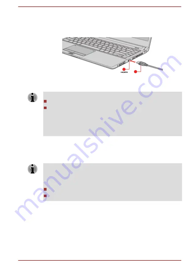
Plug the other end of the HDMI cable into the HDMI out port on your
computer.

3.

Turn the HDMI display device's power on.

Figure 4-21 Connecting the HDMI out port (R30-C/A30-C)

1

2

1. HDMI out port

2. HDMI cable

Product appearance depends on the model you purchased.

Do not plug/unplug an HDMI device under the following conditions:

The system is starting up.
The system is shutting down.

When you connect a television or external monitor to the HDMI port, the
display output device is set to HDMI.
When you unplug the HDMI cable and replug it, wait at least 5 seconds
before you replug the HDMI cable again.

Settings for display video on HDMI

To view video on the HDMI display device, be sure to configure the
following settings otherwise you might find that nothing is displayed.

Be sure to use the function key to select the display device before starting
to play video. Do not change the display device or audio device while
playing video.
Do not change the display device under the following conditions.

While data is being read or written
While communication is being carried out

Selecting HD Format

To select the display mode, do the following:
1.

Click 

Start -> Control Panel -> Appearance and Personalization ->

Display -> Change display settings -> Advanced settings -> List 
All Modes

.

2.

Select one of the modes at 

List All Modes

.

User's Manual

4-49

Summary of Contents for A30-C

Page 1: ...User s Manual R30 C R30t C A30 C A30t C R40 C A40 C ...

Page 2: ...time 2 2 Turning off the power 2 7 System Recovery 2 11 Chapter 3 The Grand Tour The Grand Tour for R30 C A30 C 3 1 The Grand Tour for R40 C A40 C 3 11 Internal Hardware Components 3 22 Power Condition Descriptions 3 24 Chapter 4 Operating Basics Using the Touch Screen only for R30t C A30t C 4 1 Using the Touch Pad 4 1 The Keyboard 4 2 Using the AccuPoint 4 5 Using the Fingerprint Sensor 4 6 Optic...

Page 3: ...sword Utility 5 8 TOSHIBA HWSetup 5 10 TOSHIBA PC Health Monitor 5 11 Using the Hard Disk Drive HDD Protection 5 12 TOSHIBA Setup Utility 5 14 Chapter 6 Troubleshooting Problem solving process 6 1 Hardware and system checklist 6 4 TOSHIBA support 6 16 Chapter 7 Appendix Specifications 7 1 AC Power Cord and Connectors 7 3 Information for Wireless Devices 7 4 Information about Intel AMT 7 15 Legal F...

Page 4: ...yond that stipulated above including conversion to digital format alteration transfer of copied material and distribution on a network without the permission of the copyright owner is a violation of copyright or author s rights and is subject to civil damages or criminal action Comply with copyright laws in making any reproduction from this manual Disclaimer This manual has been validated and revi...

Page 5: ...om of the device or box for specific information applicable to the model you purchased FCC information FCC notice Declaration of Conformity Information This equipment has been tested and found to comply with the limits for a Class B digital device pursuant to part 15 of the FCC rules These limits are designed to provide reasonable protection against harmful interference in a residential installati...

Page 6: ...e may not cause harmful interference 2 This device must accept any interference received including interference that may cause undesired operation Contact Address TOSHIBA America Information Systems Inc 9740 Irvine Boulevard Irvine California 92618 1697 Telephone 949 583 3000 This information is only applicable for the countries regions where it is required EU Declaration of Conformity This produc...

Page 7: ...e observed for so called Residential commercial and light industry environments TOSHIBA do not approve the use of this product in working environments other than the above mentioned Residential commercial and light industry environments For example the following environments are not approved Industrial Environments e g environments where a mains voltage of 380 V three phase is used Medical Environ...

Page 8: ... European Eco Design Directive with regard to requirements for standby off mode and networked standby electric power consumption of electrical and electronic household and office equipment can be found here http www toshiba eu Eco Design Disposal of products The crossed out wheeled dust bin symbol indicates that products must be collected and disposed of separately from household waste Integrated ...

Page 9: ...ly friendly disposal ensuring that the terminal contacts are covered by non conductive tape For more detailed information about the collection and recycling programmes available in your country please visit our website www toshiba eu recycling or contact your local council office or the retail outlet where you purchased the product These symbols might not stick depending on the country and region ...

Page 10: ...ne getirmektedir The number of possible pixel failures of your display is defined according to ISO 9241 307 standards If the number of pixel failures is less than this standard they will not be counted as defect or failure Battery is a consumption product since the battery time depends on the usage of your computer If the battery can not be charged at all then it is a defect or failure The changes...

Page 11: ...I DECODING AVC VC 1 AND MPEG 4 VIDEO THAT WAS ENCODED BY A CONSUMER ENGAGED IN A PERSONAL AND NONCOMMERCIAL ACTIVITY AND OR WAS OBTAINED FROM A VIDEO PROVIDER LICENSED BY MPEG LA TO PROVIDE SUCH VIDEO NO LICENSE IS GRANTED OR SHALL BE IMPLIED FOR ANY OTHER USE ADDITIONAL INFORMATION INCLUDING THAT RELATING TO PROMOTIONAL INTERNAL AND COMMERCIAL USES AND LICENSING MAY BE OBTAINED FROM MPEG LA L L C...

Page 12: ...e power button Your ENERGY STAR certified computer should be set by default to enter a low power sleep mode after a period of inactivity Simply touching the mouse or keyboard wakes the computer in seconds These sleep features can save you up to 23 per year 200 kWh per year in electricity and prevent up to 300 pounds of greenhouse gas emissions annually To learn how to adjust or activate these slee...

Page 13: ...might result in hazardous radiation exposure To prevent direct exposure to the laser beam do not try to open the enclosure Location of the Required Label Sample shown below Location of the label and manufacturing information might vary TOSHIBA SAMSUNG STORAGE TECHNOLOGY KOREA CORPORATION 14F Bldg No 102 Digital empire2 486 Sin dong Yeongtong gu Suwon si Gyeonggi do Korea 443 734 Precautions CAUTIO...

Page 14: ... computer Always operate your computer on a hard flat surface Using your computer on a carpet or other soft material can block the vents Always provide sufficient space around the computer Overheating your computer or AC adaptor could cause system failure computer or AC adaptor damage or a fire possibly resulting in serious injury Creating a computer friendly environment Place the computer on a fl...

Page 15: ... the AC adaptor disconnect it and let it cool before moving it Do not lay the AC adaptor on a material that is sensitive to heat as the material could become damaged Pressure or impact damage Do not apply heavy pressure to the computer or subject it to any form of strong impact as this can damage the computer s components or otherwise cause it to malfunction Cleaning the computer To help ensure lo...

Page 16: ... could result in damage to computer computer failure or loss of data Never transport your computer with any cards installed This might damage either the computer and or the card resulting in computer failure Always use a suitable carry case when transporting the computer When carrying your computer be sure to hold it securely so that it does not fall or hit anything Do not carry your computer by h...

Page 17: ...o not follow instructions A caution informs you that improper use of equipment or failure to follow instructions might cause data loss equipment damage or might result in minor or moderate injury Please read A note is a hint or advice that helps you make best use of your equipment User s Manual 1 14 ...

Page 18: ...ng items TOSHIBA Portable Personal Computer Battery pack preinstalled in the computer AC adaptor and power cord 2 pin plug or 3 pin plug Documentation Quickstart Instruction Manual for Safety and Comfort Warranty Information If any of the items are missing or damaged contact your dealer immediately Conventions This manual uses the following formats to describe identify and highlight terms and oper...

Page 19: ... in this manual LCD Full Model Name Short Model Name 33 8cm 13 3 PORTÉGÉ R30 C R30t C A30 C A30t C Satellite R30 C R30t C A30 C A30t C Satellite Pro R30 C R30t C A30 C A30t C R30 C A30 C 35 6cm 14 0 TECRA A40 C Satellite Pro A40 C Satellite Pro R40 C R40 C A40 C Using your computer for the first time Be sure to read the enclosed Instruction Manual for Safety and Comfort for information on the safe...

Page 20: ...ower to DC power and reduces the voltage supplied to this computer Always use the TOSHIBA AC adaptor that was included with your computer or use AC adaptors specified by TOSHIBA to avoid any risk of fire or other damage to the computer Use of an incompatible AC adaptor might cause fire or damage to the computer possibly resulting in serious injury TOSHIBA assumes no liability for any damage caused...

Page 21: ...niture or any other surface that might be marred by exposure to heat since the computer base and the surface of the AC adaptor increase in temperature during normal use Always place your computer or AC adaptor on a flat and hard surface that is resistant to heat damage Refer to the enclosed Instruction Manual for Safety and Comfort for detailed precautions and handling instructions 1 Connect the p...

Page 22: ... the power cord into a live wall outlet The DC IN Battery indicator glows Opening the display The display panel can be opened to a wide range of angles for optimal viewing While holding down the palm rest with one hand so that the main body of the computer is not raised slowly lift the display panel This will allow the angle of the display panel to be adjusted to provide optimum clarity Figure 2 5...

Page 23: ...en the display panel and the keyboard When opening or closing the display panel place one hand on the palm rest to hold the computer in place and use the other hand to slowly open or close the display panel Do not use excessive force when opening or closing the display panel Turning on the power This section describes how to turn on the power The Power indicator indicates the status Refer to the P...

Page 24: ...ode Shut Down Mode When you turn off the power in Shut Down Mode no data will be saved and the computer will boot to the main screen of the operating system the next time it is turned on 1 If you have entered data either save it to the internal storage drive or to other storage media 2 Make sure all disk disc activity has stopped before removing the disk disc If you turn off the power while a disk...

Page 25: ...a is maintained in the main memory of the computer When you turn on the power again you can continue working right where you left off When you have to turn off your computer aboard an aircraft or in places where electronic devices are regulated or controlled always shut down the computer This includes turning off any wireless communication functionalities and canceling settings that reactivate the...

Page 26: ...p Mode feature provides the following benefits Restores the previous working environment more rapidly than the Hibernation Mode feature Saves power by shutting down the system when the computer receives no input or hardware access for the time period set by the System Sleep Mode feature Allows the use of the panel power off feature Executing Sleep Mode You can enter Sleep Mode in one of following ...

Page 27: ...event data loss do not switch to Hibernation Mode while transferring data to external media such as USB devices memory media or other external memory devices Benefits of Hibernation Mode The Hibernation Mode feature provides the following benefits Saves data to the internal storage drive when the computer automatically shuts down because of a low battery condition You can return to your previous w...

Page 28: ...an also create recovery media and restore the system The following items are described in this section System Recovery Options Creating Recovery Media Restoring the pre installed software from your created Recovery Media Restoring the pre installed software from the Recovery Partition System Recovery Options The System Recovery Options feature is installed on the hard disk when shipped from the fa...

Page 29: ...or Sleep Hibernate while writing or rewriting the media Set the computer on a level surface and avoid places subjected to vibrations such as airplanes trains or cars Do not use on an unstable surface such as a stand A recovery image of the software on your computer is stored on the internal storage drive and can be copied to either disc media or USB Flash Memory by using the following steps 1 Sele...

Page 30: ...nd all data will be lost 1 Load the Recovery Media into the Optical Disc Drive or insert the recovery USB Flash Memory into one available USB port 2 Click Start Point to the arrow beside the Shut down button and then select Restart 3 Hold down the F12 key and then release this key one second after the computer is power on 4 Use the up and down cursor key to select the appropriate option from the m...

Page 31: ...n addition if you use a third party partitioning program to reconfigure the partitions on your internal storage drive you might find that it becomes impossible to set up your computer Make sure that the AC adaptor is connected during the restoring process Do not close the display panel during the restoring process When you reinstall the Windows operating system the internal storage drive will be r...

Page 32: ...y closed R30 C A30 C The following figure shows the front of the computer with the display panel in the closed position Figure 3 1 Front of the computer with display panel closed R30 C A30 C 2 4 3 7 6 5 1 1 1 Stereo speakers 5 Memory media slot 2 DC IN Battery indicator 6 Wireless communication indicator 3 Power indicator 7 Wireless WAN indicator 4 Internal storage drive indicator Provided with so...

Page 33: ...u insert an SD SDHC SDXC memory card miniSD microSD Card and MultiMediaCard Refer to the Memory media section for more information Keep foreign metal objects such as screws staples and paper clips out of the Memory media slot Foreign metal objects can create a short circuit which can cause damage and fire possibly resulting in serious injury Wireless communication indicator The Wireless communicat...

Page 34: ...as built in support for Ethernet LAN 10 megabits per second 10BASE T Fast Ethernet LAN 100 megabits per second 100BASE TX or Gigabit Ethernet LAN 1000 megabits per second 1000BASE T Refer to Operating Basics for details Do not connect any cable other than a LAN cable to the LAN jack It might cause damage or malfunction Universal Serial Bus USB 3 0 port One Universal Serial Bus port which complies ...

Page 35: ...he computer might be configured with a DVD Super Multi drive or Blu ray drive Some models are equipped with an Optical disc drive 2 6GB and 5 2GB DVD RAM media cannot be read from or written to Smart Card slot This slot allows you to install a Smart Card device Some models are equipped with a Smart Card slot Right side R30 C A30 C The following figure shows the right side of the computer Figure 3 ...

Page 36: ...metal objects can create a short circuit which can cause damage and fire possibly resulting in serious injury HDMI out port HDMI out port can connect with Type A connector HDMI cable External RGB monitor port This port provides 15 pin analog RGB port Refer to the External RGB monitor port pin assignment section for information on external RGB monitor port pin assignment This port allows you to con...

Page 37: ...ry pack refer to the Battery section Legal Footnote Battery Life For more information regarding Battery Life refer to the Legal Footnotes section Underside R30 C A30 C The following figures show the underside of the computer Ensure that the display is closed before the computer is turned over to avoid causing any damage Figure 3 5 The underside of the computer R30 C A30 C 1 4 3 2 1 5 3 2 1 Battery...

Page 38: ...is port enables connection of an optional TOSHIBA Hi Speed Port Replicator III 180W 120W described in TOSHIBA Hi Speed Port Replicator III 180W 120W Some models are equipped with the docking port Only the TOSHIBA Hi Speed Port Replicator III 180W or 120W is compatible with the docking port Do not attempt to use any other Port Replicator Keep foreign objects out of the docking port A pin or similar...

Page 39: ... 6 1 7 9 14 8 8 2 3 5 4 12 13 15 15 16 6 1 7 9 11 8 8 2 3 5 4 14 10 12 15 15 13 11 1 Wireless communication antennas not shown 9 Keyboard 2 Microphone 10 AccuPoint 3 Microphone 11 AccuPoint control buttons 4 Web Camera 12 Touch Pad ON OFF icon 5 Web Camera LED 13 TOSHIBA eco icon 6 Display screen 14 Touch Pad 7 Power button 15 Touch Pad control buttons 8 Display hinges 16 Fingerprint Sensor Provid...

Page 40: ...cation Refer to the Sound System and Video mode section for more information Some models are equipped with the built in microphone Web Camera Web Camera is a device that allows you to record video or take photographs with your computer You can use it for video chatting or video conferences using a communication tool Some models are equipped with a Web Camera Do not point the web camera directly at...

Page 41: ... hinges allow the display panel to be positioned at a variety of easy to view angles Keyboard The keyboard contains character keys control keys function keys and special Windows keys providing all the functionality of a full size keyboard Refer to the The Keyboard section for details AccuPoint A pointer control device located in the center of the keyboard is used to control the on screen pointer S...

Page 42: ...r R40 C A40 C Front with the display closed R40 C A40 C The following figure shows the front of the computer with the display panel in the closed position Figure 3 7 Front of the computer with display panel closed 2 1 1 4 3 1 Stereo speakers 3 Power indicator 2 DC IN Battery indicator 4 Wireless communication indicator Provided with some models Product appearance depends on the model you purchased...

Page 43: ...r 1 2 4 3 5 1 4 3 5 6 8 7 1 Security lock slot 5 Memory media slot 2 Optical disc drive 6 Smart Card slot 3 Universal Serial Bus USB 3 0 port 7 SIM card slot 4 Headphone Microphone jack 8 Wireless WAN indicator Provided with some models Product appearance depends on the model you purchased Security lock slot A security cable can be attached to this slot and then connected to a desk or other large ...

Page 44: ...USB device that you want to remove Keep foreign metal objects such as screws staples and paper clips out of the USB port Foreign metal objects can create a short circuit which can cause damage and fire possibly resulting in serious injury Headphone Microphone jack A 3 5 mm mini headphone microphone jack enables connection of a monaural microphone or stereo headphones Memory media slot This slot le...

Page 45: ...ion Right side R40 C A40 C The following figure shows the right side of the computer Figure 3 9 The right side of the computer 1 2 3 4 6 5 7 1 Universal Serial Bus USB 3 0 port 5 Cooling vents 2 Universal Serial Bus USB 3 0 port 6 LAN jack 3 HDMI out port 7 DC IN 19V jack 4 External RGB monitor port Provided with some models Product appearance depends on the model you purchased Universal Serial Bu...

Page 46: ...xternal RGB monitor port This port provides 15 pin analog RGB port Refer to the External RGB monitor port pin assignment section for information on external RGB monitor port pin assignment This port allows you to connect an external RGB monitor to the computer Cooling vents The cooling vents help the processor to avoid overheating Do not block the cooling vents Keep foreign metal objects such as s...

Page 47: ...r Figure 3 10 The back of the computer 1 1 Battery pack Product appearance depends on the model you purchased Battery pack The rechargeable lithium ion battery pack provides power to the computer when the AC adaptor is not connected For more detailed information on the use and operation of the battery pack refer to the Battery section Legal Footnote Battery Life For more information regarding Batt...

Page 48: ... cooling vents Keep foreign metal objects such as screws staples and paper clips out of the cooling vents Foreign metal objects can create a short circuit which can cause damage and fire possibly resulting in serious injury Carefully clean the dust on the surface of the cooling vents using a soft cloth Docking port This port enables connection of an optional TOSHIBA Hi Speed Port Replicator III 18...

Page 49: ...e display open R40 C A40 C This section shows the computer with the display panel open In order to open the display lift up the display panel and position it at a comfortable viewing angle for you User s Manual 3 18 ...

Page 50: ...as not shown 9 Keyboard 2 Microphone 10 AccuPoint 3 Microphone 11 AccuPoint control buttons 4 Web Camera 12 Touch Pad ON OFF icon 5 Web Camera LED 13 TOSHIBA eco icon 6 Display screen 14 Touch Pad 7 Power button 15 Touch Pad control buttons 8 Display hinges 16 Fingerprint Sensor Provided with some models Product appearance depends on the model you purchased User s Manual 3 19 ...

Page 51: ...ation Refer to the Sound System and Video mode section for more information Some models are equipped with the built in microphone Web Camera Web Camera is a device that allows you to record video or take photographs with your computer You can use it for video chatting or video conferences using a communication tool Some models are equipped with a Web Camera Do not point the web camera directly at ...

Page 52: ... display hinges allow the display panel to be positioned at a variety of easy to view angles Keyboard The keyboard contains character keys control keys function keys and special Windows keys providing all the functionality of a full size keyboard Refer to the The Keyboard section for details AccuPoint A pointer control device located in the center of the keyboard is used to control the on screen p...

Page 53: ... pointer and press the right button to display a menu or other function depending on the software you are using Fingerprint Sensor This sensor enables you to enroll and recognize a fingerprint Some models are equipped with a Fingerprint Sensor Internal Hardware Components This section describes the internal hardware components of your computer The actual specifications might vary depending on the ...

Page 54: ...place of a magnetic disk of the hard disk Under certain unusual conditions of prolonged non use and or exposure to high temperatures the HDD SSD might be vulnerable to data retention errors Legal Footnote Internal Storage Drive Capacity For more information regarding Internal Storage Drive Capacity refer to the Legal Footnotes section RTC battery The internal RTC battery backs up the Real Time Clo...

Page 55: ...ogy feature is enabled at factory default To turn this feature off change it in the settings accordingly in the Intel HD Graphics Control Panel You can access this control panel in the following way 1 Right click on the desktop and click Graphics Properties 2 Click Power and then click On Battery in the upper left corner 3 Click Disable under Display Power Saving Technology 4 Click Apply If you wa...

Page 56: ...pack becomes too hot while it is being charged the charge stops and the DC IN Battery indicator goes out When the temperature of the battery pack falls to a normal range charging will resume This process occurs regardless of whether the computer s power is on or off Power indicator Check the Power indicator to determine the power status of the computer The following indicator conditions should be ...

Page 57: ...ur finger down and leave it there for a few seconds This shows information to help you learn more about an item or opens a menu specific to what you are doing Pinch or stretch Touch the screen or an item with two or more fingers and then move the fingers toward each other pinch or away from each other stretch This visually zooms in or out Rotate Put two or more fingers on an item and then turn you...

Page 58: ...ouch Pad operations described in this section are only supported in certain applications The Keyboard The number of keys available on your keyboard depends on which country region your computer is configured for with keyboards being available for numerous languages There are different types of keys specifically typewriter keys function keys Windows special keys and the keypad overlay Never remove ...

Page 59: ...nction FN F1 Enters Lock computer mode To restore your desktop you need to log on again FN F2 Switches between the power plans FN F3 Switches the system to Sleep Mode FN F4 Switches the system to Hibernation Mode FN F5 Changes the active display device To use a simultaneous mode you must set the resolution of the internal display panel to match the resolution of the external display device FN F6 D...

Page 60: ...light between Timer On and Off To set up the brightness click Start All Programs TOSHIBA Tools Utilities HWSetup Click Keyboard tab and select a level under Keyboard Backlight Brightness Control To set up the timer launch the BIOS setup utility select Power Management Keyboard Backlight Control Mode and select TIMER Adjust the timer under Backlight Lighting Time This function is supported with som...

Page 61: ...ilities Accessibility Windows special keys The keyboard provides two keys that have special functions in Windows the Windows logo key activates the Start menu while the application key has the same function as the secondary right mouse button This key activates the Windows Start menu This key has the same function as the secondary right mouse button Using the AccuPoint To use the AccuPoint simply ...

Page 62: ...re hole with the peg You can buy replacement AccuPoint caps from your TOSHIBA authorized dealer Using the Fingerprint Sensor Some models have a fingerprint utility installed for the purpose of enrolling and recognizing fingerprints By enrolling the ID and password onto the fingerprint authentication feature it is no longer necessary to input the password from the keyboard Fingerprint feature enabl...

Page 63: ...ssed too hard onto the sensor and take care to ensure that the center of the fingerprint is touching the sensor before swiping Either of these conditions might cause fingerprint reading to fail Check the center of the fingerprint whorl before swiping and then ensure this is swiped along the center line of the sensor There is a possibility of authentication failures if the finger is swiped too quic...

Page 64: ...ter taking a bath Injured finger Wet finger Soiled or oily finger Extremely dry skin condition on finger Observe the following to improve the fingerprint recognition success rate Enroll two or more fingers Enroll additional fingers if a recognition failure often occurs when using already enrolled fingers Check the condition of your finger Any conditions which have changed since enrollment such as ...

Page 65: ...able to register their fingerprints due to insufficient unique characteristics in their fingerprints The recognition success rate might differ from user to user Set up Fingerprint Registration Use the following procedure when first using fingerprint authentication In use the fingerprint authentication system uses the same username and password as defined within the Windows operating system If no W...

Page 66: ... the application Delete the fingerprint data for the currently logged in user 1 In the TOSHIBA Fingerprint Utility main menu select Fingerprint Enroll 2 In the Fingerprint Enroll window it enables you to delete the fingerprint data for the currently logged in user Click an enrolled finger you want to delete Do you want to delete message box appears on the screen and then click OK If you want to de...

Page 67: ...n is not successful within a fixed duration Fingerprint Pre Boot authentication and Single Sign On feature Overview about Fingerprint Pre Boot authentication The fingerprint authentication system can be used to replace the keyboard based User Password authentication system when booting up If you do not want to use the fingerprint authentication system for password authentication when booting up bu...

Page 68: ...erprint Pre Boot authentication and Single Sign On feature It is necessary to first enroll your fingerprint with the TOSHIBA Fingerprint Utility prior to enabling and configuring the Pre Boot authentication and Single Sign On feature You should check that your fingerprint is enrolled before configuring the settings 1 Logon as Administrator means a user has administrator privileges 2 In the TOSHIBA...

Page 69: ...EXTRA Addressing Method 2 DVD R DVD RW DVD R DVD RW DVD RAM DVD R DL Format1 DVD R DL Blu ray Writer drive BDXL In addition to the above formats Blu ray Writer drive BDXL supports BD ROM BD ROM DL BD R BD R DL BD RE BD RE DL BD R TL BD R QL and BD RE TL Some types and formats of DVD R DL and DVD R DL discs may be unreadable Using the optical disc drive The full size drive provides high performance...

Page 70: ...overs the disc tray slightly Therefore you must to turn the disc at an angle when you place it in the disc tray After seating the disc however make sure it lies flat Do not touch the laser lens or any portion of its surrounding casing as this might cause misalignment Prevent foreign objects from entering the drive Check the surface of the disc tray especially the area behind the front edge of the ...

Page 71: ...ently pull the disc tray out until it is fully opened When the disc tray pops open slightly wait a moment to make sure the disc has stopped spinning before pulling the disc tray fully open 2 The disc extends slightly over the sides of the disc tray so you can grasp it Gently lift out the disc 3 Push the center of the disc tray to close it Press gently until it locks into place How to remove disc w...

Page 72: ... Blu ray discs BD R BD R DL discs can be written only once The recorded data cannot be erased or changed BD RE BD RE DL discs can be recorded more than once Writing discs TOSHIBA Disc Creator is provided as writing software with this computer This utility can be used to write data You can use the DVD Super Multi drive to write data to either CD R CD RW DVD R DVD R DL DVD RW DVD R DVD R DL DVD RW o...

Page 73: ...equipment or software Given the technological limitations of current optical disc writing drives you might experience unexpected writing or rewriting errors due to disc quality or problems with hardware devices In view of this it is good practice to make two or more copies of important data in case of any undesired change or loss of the recorded contents Before writing or rewriting Based on TOSHIB...

Page 74: ... only DVD Specifications for DVD RAM Disc for Version 2 0 Version 2 1 or Version 2 2 Panasonic Corporation for 3x and 5x speed media BD R Panasonic Corporation BD R DL Panasonic Corporation BD RE Panasonic Corporation BD RE DL Panasonic Corporation BD R TL TDK BD RE TL Panasonic Corporation Some types and formats of DVD R DL and DVD R DL discs might be unreadable Disc created in DVD R DL format4 L...

Page 75: ...a on the optical disc drive after writing is completed If the media is of poor quality or is dirty or damaged writing or rewriting errors might occur Set the computer on a level surface and avoid places subject to vibration such as airplanes trains or cars In addition do not use the computer on an unstable surface such as a stand Keep mobile phones and other wireless communication devices away fro...

Page 76: ...this added data regardless of the operating system TOSHIBA Disc Creator does not support recording to DVD RAM discs To achieve this you should use Windows Explorer or another similar utility When you back up a DVD disc be sure that the source drive supports recording to DVD R DVD R DL DVD RW DVD R DVD R DL or DVD RW media If this is not the case then the source disc might not be backed up correctl...

Page 77: ...video while watching or recording television programs using other applications Failure to do so might cause video playback or television program recording errors In addition if prescheduled recording starts during video playback it might cause video playback or television program recording errors Please view video during times when there is no recording prescheduled The resume function cannot be u...

Page 78: ...y Devices Audio If the video image is not displayed on an external display or television stop the TOSHIBA VIDEO PLAYER and change the screen resolution To change the screen resolution click Start Control Panel Appearance and Personalization Display Adjust resolution However video cannot be output to some external displays and televisions due to output or playback conditions When viewing video on a...

Page 79: ...ith a Blu ray Writer drive Playback of high bit rate content might cause frame dropping audio skipping or decrease in computer performance Close all other applications before playing back video Do not open any other applications or carry out any other operations during video playback Do not switch to Hibernation or Sleep Mode when running the TOSHIBA Blu ray Disc Player Because Blu ray Disc playba...

Page 80: ...rwise it will not play properly To play back video on an external display or TV using TOSHIBA Blu ray Disc Player use output devices like external displays or TV that have HDCP supported HDMI port The video cannot be displayed on an external display or TV connected to the RGB connector The Blu ray Disc movie can be played only on internal LCD displays or external devices connected via an HDMI outp...

Page 81: ...er might start automatically Click Start All Programs TOSHIBA Media Entertainment TOSHIBA Blu ray Disc Player Operating TOSHIBA Blu ray Disc Player Notes on using TOSHIBA Blu ray Disc Player Screen display and available features might vary amongst Blu ray Videos and scenes If the menu is opened in the Display Area using the Control Panel s Top Menu or Menu buttons Touch Pad and mouse menu operatio...

Page 82: ... the real time clock and calendar will stop working You can change the Real Time Clock settings in the TOSHIBA Setup Utility Refer to Real Time Clock for further information The RTC battery of the computer must be replaced only by your dealer or by a TOSHIBA service representative The battery can explode if not properly replaced used handled or disposed of Dispose of the battery as required by loc...

Page 83: ...s of battery power remain If you continue to use the computer while the DC IN Battery indicator flashes the computer enters Hibernation Mode so that you do not lose any data and automatically turn itself off You must recharge the battery pack when it becomes discharged Procedures To recharge a battery pack connect the AC adaptor to the DC IN 19V jack and plug the other end into a working outlet Th...

Page 84: ...ature of between 5 C to 35 C 41 F to 95 F The battery is nearly completely discharged In this instance leave the AC adaptor connected for a few minutes and the battery should begin charging The DC IN Battery indicator might show a rapid decrease in battery operating time when you try to charge a battery under the following conditions The battery has not been used for a long time The battery has co...

Page 85: ...essor speed Screen brightness Internal storage drive power off period How often and for how long you use the internal storage drive and external disk drives for example optical disc How much charge the battery contained to begin with How you use optional devices such as a USB device to which the battery supplies power Where you store your programs and data Whether you close the display panel when ...

Page 86: ...pack is fully discharged However if the DC IN Battery indicator flashes or there is some other warning to indicate a low battery condition go to Step 4 4 Connect the AC adaptor to the DC IN 19V jack of the computer and to a wall outlet that is supplying power The DC IN Battery indicator glows amber to indicate that the battery pack is being charged However if DC IN Battery indicator does not glow ...

Page 87: ...ery release latch and cause injuries Removing the battery pack To remove a discharged battery do the following 1 Save your work 2 Click Start and click Shut down Ensure that the Power indicator is off 3 Remove all cables and peripherals that are connected to the computer 4 Close the display panel and turn the computer upside down 5 Slide the battery lock into its unlocked position 6 Slide and hold...

Page 88: ...away from the office Installing a SIM card R30 C A30 C To install a SIM card do the following 1 Click Start and click Shut down Ensure that the Power indicator is off 2 Remove the AC adaptor and all cables and peripherals connected to the computer 3 Close the display panel 4 Turn the computer upside down and remove the battery pack 5 Locate the SIM card slot 6 To pop the SIM card tray partially op...

Page 89: ...Turn the computer upside down and remove the battery pack 4 To pop the SIM card tray partially open insert a slender object about 10mm diameter 0 8mm such as a straightened paper clip into the eject hole Gently pull to open the SIM card tray 5 Remove the SIM card from the SIM card tray 6 Insert the SIM card tray back into the SIM card slot Wireless WAN Device R40 C A40 C Some models are equipped w...

Page 90: ...M card into the SIM card tray with the metal connectors facing up 8 Insert the SIM card tray into the SIM card slot and push the center of the tray to close it Press gently until it locks into place 9 Install the battery pack Figure 4 10 Installing the SIM Card R40 C A40 C 1 2 1 SIM card tray 2 SIM card Product appearance depends on the model you purchased Never allow metal objects such as screws ...

Page 91: ...n might happen Your current location might not be shown depending on the status of GPS or the location If you are obtaining your current location information from the computer your current location might not be detected due to the information accuracy Specifically your current location might not be detected in the following places or situations Inside or directly under a building Inside a bag or b...

Page 92: ...cause malfunction or electric shock Additional memory module is a precision electronic component that might be fatally damaged by static electricity Since the human body can carry static electricity it is important that you discharge yourself before touching or installing any additional memory modules To discharge your body s static electricity simply touch any metal close to you with bare hands U...

Page 93: ...fingernail or a thin object under the cover and lift it off Figure 4 11 Removing the memory module cover 1 1 2 1 Screws 2 Memory module cover Product appearance depends on the model you purchased User s Manual 4 37 ...

Page 94: ...e and fire possibly resulting in serious injury Do not touch the connectors on the memory module or on the computer Debris on the connectors might cause memory access problems The slot A is reserved for the first memory module Use the slot B for expanded memory If only one module is installed use the slot A Align the grooves along the edges of the memory module with the locking tabs on the connect...

Page 95: ...y System Removing a memory module To remove the memory module do the following 1 Click Start and click Shut down Ensure that the Power indicator is off 2 Remove the AC adaptor all cables and peripherals connected to the computer 3 Close the display panel 4 Turn the computer upside down and remove the battery pack 5 Loosen the screw securing the memory module cover in place Note that the screw is a...

Page 96: ...hes Product appearance depends on the model you purchased 9 Seat the memory module cover in place and secure it with the screw Ensure that the memory module cover is firmly closed 10 Install the battery pack 11 Turn your computer over 12 Connect the AC adaptor and turn the computer on LAN The computer has built in support for Ethernet LAN 10 megabits per second 10BASE T Fast Ethernet LAN 100 megab...

Page 97: ...cond 100BASE TX be sure to connect with a CAT5 cable or higher You cannot use a CAT3 cable If you are using Ethernet LAN 10 megabits per second 10BASE T you can connect with a CAT3 or higher cable Connecting the LAN cable To connect the LAN cable do the following Connect the AC adaptor before connecting the LAN cable The AC adaptor must remain connected during LAN use If you disconnect the AC Adap...

Page 98: ...with a memory media slot that can accommodate some kinds of memory media with various memory capacities so that you can easily transfer data from devices such as digital cameras and Personal Digital Assistants Keep foreign objects out of the memory media slot Never allow metal objects such as screws staples and paper clips to enter the computer or Keyboard Foreign metal objects can create a short ...

Page 99: ...pear the same externally However the logo on memory cards is different so pay careful attention to the logo when purchasing The SD memory card logo is The SDHC memory card logo is The SDXC memory card logo is The maximum capacity of SD memory cards is 2 GB The maximum capacity of SDHC memory cards is 32 GB The maximum capacity of SDXC memory cards is 128 GB Memory media format New media cards are ...

Page 100: ...rotect switch to the lock position if you do not want to record data Memory cards have a limited lifespan so it is important to back up important data Do not write to a card if the battery power is low Low power might affect writing accuracy Do not remove a card while read write is in progress For more details on using memory cards see manuals accompanying the cards About the write protect feature...

Page 101: ...memory media do not touch the metal contacts You might expose the storage area to static electricity which can destroy data Do not turn off the computer or switch to Sleep Mode or Hibernation Mode while files are being copied Failure to do so might cause data loss Removing memory media The following instructions apply to all types of supported media devices To remove memory media do the following ...

Page 102: ...orded These cards can be used for a wide variety of applications including telephone related and electronic monetary payments This section contains information on the proper use of the Smart Card slot and it is strongly recommended that you read it before operating the computer Some models are equipped with a Smart Card slot Your computer supports ISO7816 3 asynchronous cards support protocols are...

Page 103: ...heck the configuration in Windows to ensure that it is correct Removing a Smart Card To remove a Smart Card do the following 1 Click the Safely Remove Hardware and Eject Media icon on the Windows Taskbar Before removing the Smart Card confirm that the Smart Card is not working with any program or system Be careful not to bend the Smart Card while removing it from the computer 2 Point to Smart Card...

Page 104: ...ognizes the monitor and determines whether it is a color or monochrome device When displaying desktop on an external RGB monitor desktop is sometimes displayed on the center of the monitor with black bars around desktop with small size At that time read the manual of the monitor and set the display mode which is supporting at the monitor Then it will be displayed with suitable size with correct as...

Page 105: ...efore you replug the HDMI cable again Settings for display video on HDMI To view video on the HDMI display device be sure to configure the following settings otherwise you might find that nothing is displayed Be sure to use the function key to select the display device before starting to play video Do not change the display device or audio device while playing video Do not change the display devic...

Page 106: ... play on the external displays via Intel WiDi Changing the external playback settings After one or more external displays are connected the operating system can automatically detect identify and set up the display settings You can also manually manage how the external displays work and change the display settings by pressing P while holding down the Windows key If you disconnect the external displ...

Page 107: ...ator or on your computer some software might show different type of ports which you connected When connecting an AC Adaptor to the Port Replicator use only the AC Adaptor included with Port Replicator Do not use the computer s AC Adaptor Refer to the Port Replicator s User s Manual for more details To dock your computer in the Port Replicator do the following 1 For R30 C A30 C Align the top left o...

Page 108: ...e the AC adaptor is always connected to the TOSHIBA Hi Speed Port Replicator III 180W 120W while in use Otherwise the Port Replicator will stop working possibly resulting in data loss Some models support multiple display function if equipped with a TOSHIBA Hi Speed Port Replicator III 180W 120W The port replicator supports a maximum of two external displays For each VIDEO panel only one port can f...

Page 109: ...onnecting the security lock To connect a security cable to the computer do the following 1 Turn the computer so the security lock slot faces you 2 Align the security cable with the lock slot and secure it in place Figure 4 24 Security lock R30 C A30 C 2 1 Figure 4 25 Security lock R40 C A40 C 2 1 1 Security lock slot 2 Security lock Product appearance depends on the model you purchased Optional TO...

Page 110: ...olume Mixer utility right click on the speaker icon on the Windows Taskbar and then select Open Volume Mixer from the sub menu To adjust the volume level of speakers or headphones move the Speakers slider To adjust the volume level of an application that you are using move the slider for the corresponding application Microphone Level To change the microphone recording level do the following 1 Righ...

Page 111: ...ancement for clear and intelligible vocals Bass enhancement for rich low frequency production High frequency definition for crisp details Consistent volume level across content To access the utility click Start All Programs DTS Inc DTS Studio Sound U S patents apply to this product See http patents dts com Manufactured under license from DTS Licensing Limited Realtek HD Audio Manager You can confi...

Page 112: ...e Microphone selection To change the type of headphone or microphone do the following 1 Plug a headphone or microphone into the headphone microphone combo jack 2 Double click on the circle button in the right side of the Realtek HD Audio Manager main screen 3 Select one from the device list for the device you plugged into Video mode Video mode settings are configured via the Screen Resolution dial...

Page 113: ... Tool displays basic system configuration information and allows the functionality of some of the computer s built in hardware devices to be tested TOSHIBA Accessibility The TOSHIBA Accessibility utility provides support to movement impaired users when they need to use the function keys In use the utility allows you to make the FN key sticky that is you can press it once release it and they press ...

Page 114: ...tart All Programs TOSHIBA Media Entertainment Disc Creator TOSHIBA Password Utility This utility allows you to set a password in order to restrict access to the computer TOSHIBA eco Utility This computer is equipped with eco mode This mode slightly lowers performance of some devices to reduce electric power consumption You can realize measurable power savings by using it continuously TOSHIBA eco U...

Page 115: ...ther alerts from TOSHIBA that are specific to your computer system and its programs When enabled this application periodically transmits to our servers a limited amount of system information which will be treated in strict accordance with the rules and regulations as well as applicable data protection law To access this utility click Start All Programs TOSHIBA Support Recovery Service Station TOSH...

Page 116: ...ecified in the Power Options System automatic Sleep Hibernation Mode 1 This feature automatically shuts down the system into either Sleep Mode or Hibernation Mode when there is no input or hardware access for a specified time This can be specified in the Power Options Power on password Two levels of password security supervisor and user are available to prevent unauthorized access to your computer...

Page 117: ... Mode depending on the external devices connected to the USB ports Please note that the USB port on the keyboard dock does not support this function For example if a mouse or USB keyboard is connected clicking the mouse button or pressing the keyboard will wakeup the computer Heat dispersal 1 To protect against overheating the processor is equipped with an internal temperature sensor which activat...

Page 118: ... supplied to compatible ports even when the power of the computer is turned OFF USB bus power DC5V is similarly supplied to the external devices which are connected to the compatible ports However some external devices cannot be charged solely by supplying USB bus power DC5V As for the specifications of the external devices contact the device manufacturer or check the specifications of the externa...

Page 119: ...or the compatible USB ports The default state is disabled Power supply mode settings Your PC has multiple charging modes so that many different USB devices can be supported for Sleep and Charge function Auto Mode Default is suitable for a wide range of digital audio players However determining which mode is suitable for your USB device is unknown without trying Try each mode using the following pr...

Page 120: ... Be sure to keep the media in a safe place When entering the character string to register the password enter from the keyboard character by character and do not enter as ASCII code or copy and paste the character string In addition ensure that the registered password is correct by outputting the character string to the password file When entering a password do not enter any characters for example ...

Page 121: ...ly reflected For more information on shutting down or restarting the computer refer to Turning on the power Supervisor Password If you set a Supervisor Password some functions might be restricted when a user logs on with the User Password You can start the Supervisor Password utility by accessing the following folder and then double click TOSPU exe C Program Files TOSHIBA PasswordUtility or C Prog...

Page 122: ...dition there are also three buttons OK Cancel and Apply OK Accepts your changes and closes the TOSHIBA HWSetup window Cancel Closes the window without accepting your changes Apply Accepts all your changes without closing the TOSHIBA HWSetup window Some options shown in grey are possible to confirm their status TOSHIBA HWSetup screen might have the following tabs General Allows you to view the curr...

Page 123: ...ations or status changes that is number of power button and FN key combination uses AC adaptor battery for models with battery LCD fan for models with fan HDD SSD sound volume wireless communication functionalities and USB information usage of TOSHIBA provided features applications that is settings operation install state and launch times date of initial system use and also computer and device usa...

Page 124: ...itions and to the use and sharing of the collected information Once the program is enabled the TOSHIBA PC Health Monitor screen is displayed and the program begins monitoring system functions and collecting information A message is displayed if any changes which might interfere with the operation of the program are detected Follow the instructions displayed on screen in the message Using the Hard ...

Page 125: ...e Move the slider to the right to enable notification when viberation is detected System Tray Icon Move the slider to the right to show HDD Protection icon in the Taskbar There are the following conditions for HDD Protection icon Normal TOSHIBA HDD Protection is enabled Protection TOSHIBA HDD Protection is active The HDD head is in a safe position OFF TOSHIBA HDD Protection is disabled Detection L...

Page 126: ...r vibration of the computer When HDD Protection detects computer vibration the HDD head is parked and the 3D object disk rotation stops When the head is un parked the disk begins to rotate again Click 3D Viewer button to start This 3D object virtually represents the computer s internal HDD This representation might vary from the actual number of disks disk rotation head movement part size shape an...

Page 127: ...lease this key one second after the computer is power on To save the changes and exit the utility press the F10 key and proceed by selecting Yes or select Exit Exit Saving Changes Yes The computer restarts immediately User s Manual 5 15 ...

Page 128: ...n this chapter are meant only as a guide they are not definitive problem solving techniques In reality many problems can be solved simply but a few might require help from TOSHIBA Support If you find you need to consult others be prepared to describe the problem in as much detail as possible Preliminary checklist You should always consider the simplest solution first The items detailed in this che...

Page 129: ...racters Make a screenshot of the current display and if possible look up the messages in the documentation included with the computer software or operating system Check that all connecting cables are correctly and firmly attached as loose cables can cause erroneous or intermittent signals Do any indicators light if so which ones what color are they and do they stay on or blink Write down what you ...

Page 130: ...ds before turning on the power again by pressing the power button Your program stops responding If you are working with a program that suddenly freezes all operations chances are the program has stopped responding You can exit the failed program without shutting down the operating system or closing other programs To close a program that has stopped responding 1 Press CTRL ALT and DEL simultaneousl...

Page 131: ...SHIBA Setup Utility F12 Boot Menu 0 zero Recovery options If your computer starts to load the Operating System instead of desired advanced options do the following 1 Click Start Point to the arrow beside the Shut down button and then select Restart 2 Hold down the corresponding key and then release this key one second after the computer is power on 3 Follow the on screen instructions to proceed Ha...

Page 132: ...e trouble turning on the computer with the AC adaptor connected check the status of the DC IN Battery indicator Refer to the Power Condition Descriptions section for further information Problem Procedure AC adaptor does not power the computer Check the connections to make sure that the power cord adaptor is firmly connected to the computer and a working power outlet Check the condition of the cord...

Page 133: ...tery taking care to ensure that it is securely seated in the computer Check the DC IN Battery indicator If it does not glow allow the computer to charge the battery for at least twenty minutes If the DC IN Battery indicator starts to glow after this period allow the battery to continue to charge for at least another twenty minutes before turning on the computer However if the indicator still does ...

Page 134: ...d BIOS Problem Procedure The computer cannot be powered on Disconnect the AC adaptor and remove the battery for several seconds Then reinstall the battery and reconnect the AC adaptor After that press the power button If it does not work press the power button twice again If it still does not work press and hold the power button for 12 seconds Real Time Clock RTC information might be cleared if th...

Page 135: ...nitor Markings appear on the computer s display panel These marks might have come from contact with the keyboard and Touch Pad while the display panel has been closed Try to remove the marks by gently wiping the display panel with a clean dry cloth or if this fails with a good quality LCD screen cleaner In this latter instance you should always follow the instructions with the screen cleaner and a...

Page 136: ...ress gently until it clicks into place Open the disc tray and make sure the disc is properly seated It should lie flat with the label facing up A foreign object in the disc tray might block laser light from reading the disc Make sure there is no obstruction Remove any foreign object Check whether the disc is dirty If it is wipe it with a clean cloth dipped in water or a neutral cleaner Memory Medi...

Page 137: ... system might be busy Try moving the mouse again after waiting a short while Double tapping Touch Pad does not work In this instance you should initially try changing the double click speed setting within the Mouse Control utility 1 To access this utility click Start Control Panel Hardware and Sound Mouse 2 Within the Mouse Properties window click the Buttons tab 3 Set the double click speed as re...

Page 138: ...tting within the Mouse Control utility 1 To access this utility click Start Control Panel Hardware and Sound Mouse 2 Within the Mouse Properties window click the Buttons tab 3 Set the double click speed as required and click OK The mouse pointer moves too fast or too slow In this instance you should initially try changing the speed setting within the Mouse Control utility 1 To access this utility ...

Page 139: ...in the TOSHIBA HWSetup When there is a current overflow of the external device connected to the compatible port USB bus power DC5V supply might be stopped for safety reasons When this happens disconnect an external device if some external devices are connected After that turn the power of the computer ON OFF to restore the function If this function cannot be still used even if only one external de...

Page 140: ...p and Charge function or change to disable the Sleep and Charge function The USB Wakeup function does not work When USB Sleep and Charge function is enabled the USB WakeUp function does not work for ports that support the Sleep and Charge function In that case use an USB port that does not have the USB Sleep and Charge function or change to disable USB Sleep and Charge function Sound system In add...

Page 141: ...g the contrast and brightness controls on the external monitor Press the function key in order to change the display priority and ensure that it is not set for the internal display only Check to see if the external monitor is connected When the external monitor is set as the primary display device in extended desktop mode it does not display when the computer wakes up from Sleep Mode if the extern...

Page 142: ...roblem Procedure Cannot access Wireless LAN Make sure that the wireless communication function of the computer is on If problems persist contact your LAN administrator Bluetooth Problem Procedure Cannot access Bluetooth device Check to ensure that the wireless communication function of the computer is on Check to ensure that the Bluetooth Manager application is running on the computer and that pow...

Page 143: ...n supplied with your software and or peripheral devices If a problem occurs when you are running software applications consult the software documentation for troubleshooting suggestions and consider calling the software company s technical support department for assistance Consult the reseller or dealer from where you purchased your computer and or software they are your best resource for current ...

Page 144: ...illimeters Approximately 316 w x 229 d x 24 4 h millimeters touch screen models not including parts that extend beyond the main body Physical Dimensions R40 C A40 C The following physical dimensions do not include parts that extend beyond the main body The physical dimensions vary depending on the model you purchased Size Approximately 340 1 w x 244 1 d x 23 8 h millimeters not including parts tha...

Page 145: ...ernal RGB monitor port pin assignment 6 10 1 5 15 11 Pin Signal Name Description I O 1 CRV Red Video Signal O 2 CGV Green Video Signal O 3 CBV Blue Video Signal O 4 Reserved Reserved 5 GND Ground 6 GND Ground 7 GND Ground 8 GND Ground 9 5V Power Supply 10 GND Ground 11 Reserved Reserved 12 SDA Serial Data Signal I O 13 HSYNC Horizontal Sync Signal O 14 VSYNC Vertical Sync Signal O User s Manual 7 ...

Page 146: ...nimum 2 5 amperes Certification agencies China CQC U S and Canada UL listed and CSA certified No 18 AWG Type SVT or SPT 2 Australia AS Japan DENANHO Europe Austria OVE Italy IMQ Belgium CEBEC The Netherlands KEMA Denmark DEMKO Norway NEMKO Finland FIMKO Sweden SEMKO France LCIE Switzerland SEV Germany VDE United Kingdom BSI In Europe two conductors power cord must be VDE type H05VVH2 F or H03VVH2 ...

Page 147: ...lity The Wireless LAN is compatible with other LAN systems Direct Sequence Spread Spectrum DSSS Orthogonal Frequency Division Multiplexing OFDM radio technology and is compliant to The IEEE 802 11 Standard on Wireless LANs Revision a b g n b g n or Revision a b g n ac as defined and approved by the Institute of Electrical and Electronics Engineers Bluetooth Modules are designed to be interoperable...

Page 148: ...gnetic energy The level of energy emitted by wireless products however is far much less than the electromagnetic energy emitted by wireless devices like for example mobile phones Because wireless products operate within the guidelines found in radio frequency safety standards and recommendations TOSHIBA believes wireless products are safe for use by consumers These standards and recommendations re...

Page 149: ... waves can cause malfunction of such equipment possibly resulting in serious injury It might not be possible to make a network connection to a specified network name using the ad hoc network function If this occurs the new network has to be configured for all computers connected to the same network in order to re enable network connections Make sure to use new network name Security TOSHIBA strongl...

Page 150: ...rference Requirements This device is restricted to indoor use due to its operation in the 5 15 to 5 25GHz frequency range High power radars are allocated as primary users i e priority users of the bands 5 25 to 5 35GHz and 5 65 to 5 85GHz and that these radars could cause interference and or damage to LE LAN devices Bluetooth wireless technology Some computers in this series have Bluetooth wireles...

Page 151: ...er electronic devices that use Bluetooth other than TOSHIBA notebook computers Release Notes related to the Bluetooth Stack for Windows by TOSHIBA 1 Fax application software Please be aware that there is some fax application software that you cannot use on this Bluetooth Stack 2 Multi user considerations The use of Bluetooth is not supported in a multi user environment This means that when you use...

Page 152: ... own premises For public use a general authorization is required Luxembourg Implemented General authorization required for network and service supply Norway Implemented This subsection does not apply for the geographical area within a radius of 20 km from the centre of Ny Alesund Russian Federation Only for indoor applications Restrictions for Use of 5150 5350MHz Frequencies in Europe Italy For pr...

Page 153: ...e used outside own premises Luxembourg Implemented General authorization required for network and service supply Russian Federation Limited e i r p 100mW Permitted to use only for indoor applications closed industrial and warehouse areas and on board aircraft 1 Permitted to use for local networks of aircraft crew service communications on board aircraft in area of the airport and at all stages of ...

Page 154: ...mobiles utilisant les mêmes canaux Les utilisateurs devraient aussi être avisés que les utilisateurs de radars de haute puissance sont désignés utilisateurs principaux c à d qu ils ont la priorité pour les bandes 5 25 5 35GHz et 5 65 5 85GHz et que ces radars pourraient causer du brouillage et ou des dommages aux dispositifs LAN EL The term IC before the equipment certification number only signifi...

Page 155: ... radio frequency devices Article 14 The low power radio frequency devices shall not influence aircraft security and interfere legal communications If found the user shall cease operating immediately until no interference is achieved The said legal communications means radio communications is operated in compliance with the Telecommunications Act The low power radio frequency devices must be suscep...

Page 156: ...act an authorized TOSHIBA service provider if you have problems with interference caused by this product to Other Radio Stations 2 Indication for Wireless LAN The indication shown below appears on this equipment 1 2 3 4 5 1 2 4 This equipment uses a frequency of 2 4 GHz 2 DS This equipment uses DS SS modulation 3 OF This equipment uses OFDM modulation 4 4 The interference range of this equipment i...

Page 157: ...uipment 8260NGW DSP Research Inc Approval Number D150069003 Intel Dual Band Wireless AC 3165 The Name of the radio equipment 3165NGW DSP Research Inc Approval Number D150008003 The following restrictions apply Do not disassemble or modify the device Do not install the embedded wireless module into other device Radio approvals for wireless devices This equipment is approved to the radio standard by...

Page 158: ... in a situation where no system administrator presents it is strongly recommended that you turn off the AMT function before connecting to a network If the AMT function is NOT turned off there is a danger that the management of AMT function will be abused by other parties which possibly lead to the leak of sensitive and or proprietary information data loss HDD SSD erasure or file overwritten First ...

Page 159: ...on the US keyboard layout The following table shows examples of the special characters in US keyboard layout Special character you want to input Corresponding number key SHIFT key a number key 1 2 3 4 5 6 7 8 9 0 3 Select Intel R AMT Configuration and press the Enter key 4 Select Manageability Features Selection and press the Enter key 5 Select Disabled and press the Enter key 6 Press the Y key an...

Page 160: ...ngeable in BIOS setup utility Consult with your system administrator about details AMT function cannot be operated using a USB LAN adaptor The useable system memory for models equipped with the AMT function is 16 64 MB less than that of models not equipped with the AMT function The amount of the difference depends on the amount of memory installed Notes for system administrators Intel AMT is enabl...

Page 161: ... might vary depending on the specific computer model contact TOSHIBA support for details CPU performance might also vary from specifications due to design configuration Under some conditions your computer product might automatically shut down This is a normal protective feature designed to reduce the risk of lost data or damage to the product when used outside recommended conditions To avoid risk ...

Page 162: ...the operating system Even though some tools might display the actual physical memory built into your computer the memory available to the operating system is still approximately 3 GB only Computers configured with a 64 bit operating system can address 4 GB or more of system memory Battery Life Battery life might vary considerably depending on product model configuration applications power manageme...

Page 163: ...ly optimized when operating in AC power mode and might decrease considerably when operating in battery power mode Total Available Graphics Memory is the total of as applicable Dedicated Video Memory System Video Memory and Shared System Memory Shared System Memory varies depending on system memory size and other factors Wireless LAN The transmission speed over the wireless LAN and the distance ove...

Page 164: ...features or use of this software must display the following acknowledgment This product includes software developed by the OpenSSL Project for use in the OpenSSL Toolkit http www openssl org 4 The names OpenSSL Toolkit and OpenSSL Project must not be used to endorse or promote products derived from this software without prior written permission For written permission please contact openssl core op...

Page 165: ...o all code found in this distribution be it the RC4 RSA lhash DES etc code not just the SSL code The SSL documentation included with this distribution is covered by the same copyright terms except that the holder is Tim Hudson tjh cryptsoft com Copyright remains Eric Youngs and as such any Copyright notices in the code are not to be removed If this package is used in a product Eric Young should be...

Page 166: ...NCIDENTAL SPECIAL EXEMPLARY OR CONSEQUENTIAL DAMAGES INCLUDING BUT NOT LIMITED TO PROCUREMENT OF SUBSTITUTE GOODS OR SERVICES LOSS OF USE DATA OR PROFITS OR BUSINESS INTERRUPTION HOWEVER CAUSED AND ON ANY THEORY OF LIABILITY WHETHER IN CONTRACT STRICT LIABILITY OR TORT INCLUDING NEGLIGENCE OR OTHERWISE ARISING IN ANY WAY OUT OF THE USE OF THIS SOFTWARE EVEN IF ADVISED OF THE POSSIBILITY OF SUCH DA...

Page 167: ...mmercial products We disclaim all warranties covering The FreeType Project and assume no liability related to The FreeType Project Finally many people asked us for a preferred form for a credit disclaimer to use in compliance with this license We thus encourage you to use the following text Portions of this software are copyright C year The FreeType Project www freetype org All rights reserved Ple...

Page 168: ...ze others to exercise some or all of the rights granted herein subject to the following conditions Redistribution of source code must retain this license file FTL TXT unaltered any additions deletions or changes to the original files must be clearly indicated in accompanying documentation The copyright notices of the unaltered original files must be preserved in all copies of source files Redistri...

Page 169: ...pe Project you indicate that you understand and accept all the terms of this license 4 Contacts There are two mailing lists related to FreeType freetype nongnu org Discusses general use and applications of FreeType as well as future and wanted additions to the library and distribution If you are looking for support start in this list if you haven t found anything to help you in the documentation f...

Page 170: ...omputer 1 12 Cooling vents 3 5 3 7 3 15 3 17 D DC IN Battery indicator 3 24 Display automatic power off 5 4 opening 2 5 screen 3 10 3 21 Documentation list 2 1 Dual Pointing Device AccuPoint 4 5 Touch Pad 6 10 E Equipment checklist 2 1 External monitor problems 6 14 G Graphics Processing Unit 3 24 H HW Setup accessing window K Keyboard function keys 4 3 Function keys F1 F12 4 3 problems 6 7 Window...

Page 171: ...7 turning on 2 6 Problems AC power 6 5 Analyzing the problem 6 2 Battery 6 5 Dual Pointing device 6 10 External monitor 6 14 Hardware and system checklist 6 4 HDD 6 8 6 9 Internal display panel 6 8 Keyboard 6 7 Memory Media Card 6 9 Overheating power down 6 5 Power 6 4 Real Time Clock 6 7 Sound system 6 13 TOSHIBA support 6 16 Touch Pad 6 10 USB device 6 12 USB mouse 6 11 R Recovery hard disk driv...

Page 172: ...utomatic power off 5 4 T TOSHIBA Disc Creator 4 19 TOSHIBA HDD SSD Alert Utility 5 3 TOSHIBA PC Diagnostic Tool 5 1 Touch Screen 4 1 U USB device problems 6 12 V Video mode 4 56 Video RAM 3 23 W Web Camera 3 9 3 20 Wireless communication 7 6 User s Manual Index 3 ...

Reviews: