background image


64 


4200FA Installation and Operation Manual 

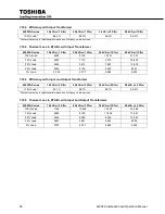
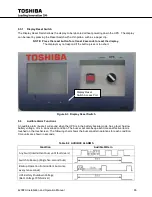
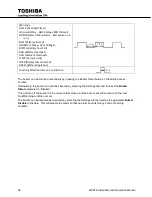
NOTE: On-Line/Fault LEDs - Appear Amber if Green and Red flash concurrently. 


Operator Manual Controls 

9.3


Bypass/Online Switch 

9.4

Switches the UPS between On-Line and Bypass modes. 


EPO (Emergency Power Off) Function 

9.5

These units are equipped with a front panel mounted EPO switch.  

This safety feature enables quick shutdown of the UPS AC output and battery circuits.    

The EPO function is initiated by pressing the switch to the closed “shutdown” position.  The effect of using 
the EPO switch is the same whether the UPS is in the AC Input Mode, Battery Backup Mode, or the 
Bypass Mode.  See ‘EMERGENCY OFF’ screen.  

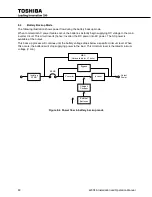
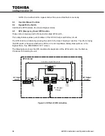
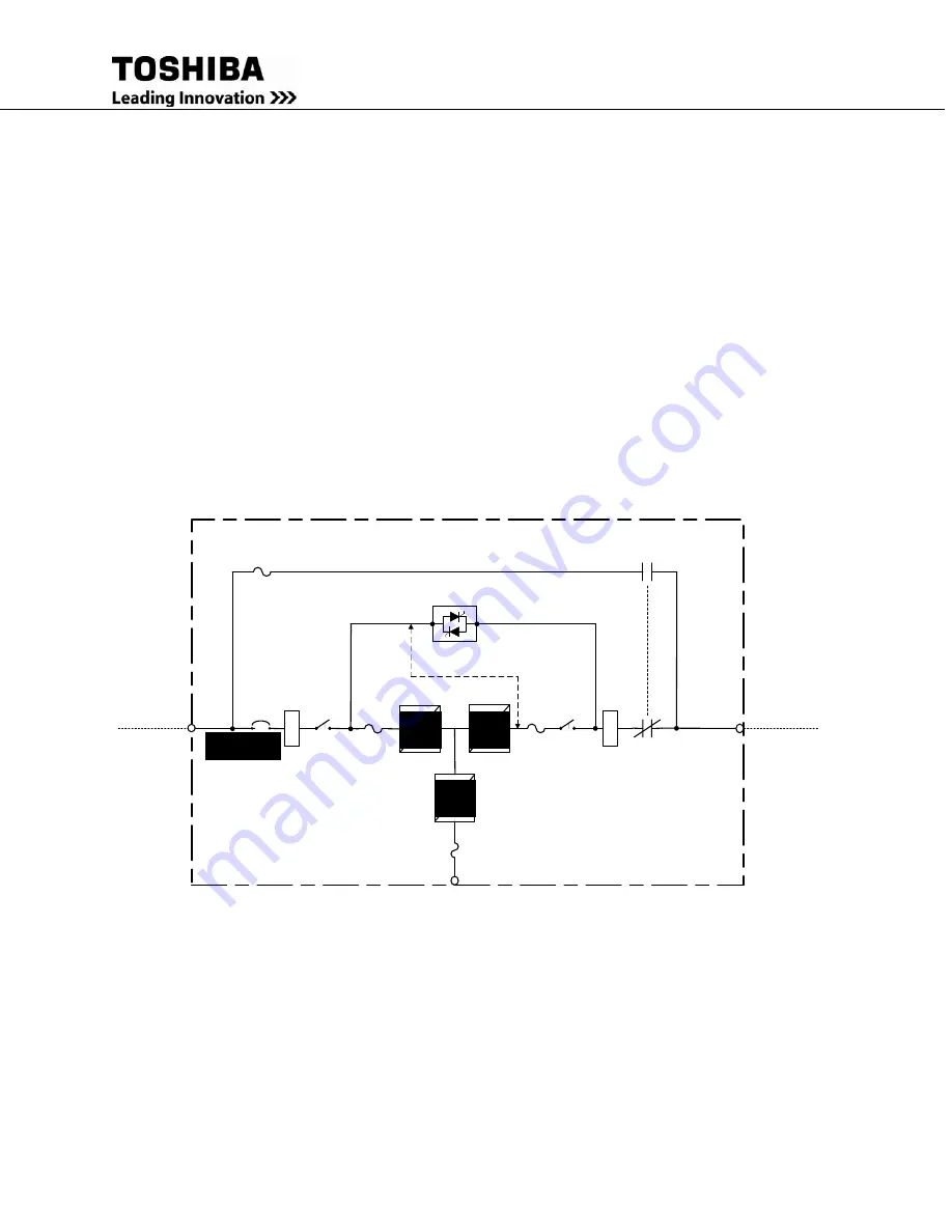
The following figure shows the UPS condition after application of the EPO switch.  Use the Start-up 
Procedure for restarting the unit. 


UPS Cabinet 

AC Output


3Ph/4W

Static Switch Bypass

AC Input 

3Ph/4W

Maintenance Bypass Rotary Switch

Converter

DC Chopper/

Charger 

SYNC

Inverter

Make

-Before

-Break

High 

Freq. 

Filter

High 

Freq. 

Filter

Input 

Contactor

Output 

Contactor

MCCB

OFF

OFF

OFF

TRIPPED


Figure 9-2  Effect of EPO Activation 


Summary of Contents for 4200FA Series

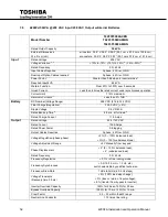
Page 1: ...UNINTERRUPTIBLE POWER SYSTEM UPS 4200FA INSTALLATION AND OPERATION MANUAL Three Phase 15 25 30 50 kVA UPS Doc No 53878 013 Date June 2013 ...

Page 2: ...4200FA Installation and Operation Manual ...

Page 3: ...anual 3 4200FA INSTALLATION AND OPERATION MANUAL Three Phase 15 25 30 50 kVA UPS FOR all 15 50 kVA MODELS WITH TOUCHSCREEN INTERFACE TOSHIBA INTERNATIONAL CORPORATION INDUSTRIAL DIVISION 13131 West Little York Road Houston TX 77041 9990 ...

Page 4: ...ment or to provide for every possible contingency concerning installation operation or maintenance Should further information be required or if problems arise which are not covered sufficiently contact your Toshiba sales office The contents of this instruction manual shall not become a part of or modify any prior or existing agreement commitment or relationship The sales contract contains the enti...

Page 5: ...PS Product Manager Please complete the following information for your records Unless otherwise specified on the warranty card the warranty period for the UPS or UPS part is 36 months from the shipment date see bill of lading Unless otherwise specified on the warranty card the warranty period for a UPS battery is 24 months from the shipment date see bill of lading Keep this manual with the UPS equi...

Page 6: ...her product or trade references appearing in this manual are registered trademarks of their respective owners TOSHIBA shall not be liable for technical or editorial omissions or mistakes in this manual Nor shall it be liable for incidental or consequential damages resulting from the use of information contained in this manual This manual is copyrighted No part of this manual may be photocopied or ...

Page 7: ... Base and Seismic model 15 25 30 50 kVA UPS without Casters 16 4 7 Storage of UPS equipment 17 4 8 Disposal 17 4 9 5 Installation Precautions 18 Equipment Placement 18 5 1 System Preparation Pre Power 19 5 2 Operating Precautions 19 5 3 6 UPS Connections 20 Power Connections 20 6 1 6 1 1 Power Connections 15 25 30 kVA with Internal Batteries 20 6 1 2 Power Connections 15 25 30 kVA with Internal Tr...

Page 8: ...formers 55 7 10 2 Efficiency with Input Transformer 56 7 10 3 Thermal Loss in BTU Hr with Input Transformer 56 7 10 4 Efficiency with Input and Output Transformer 56 7 10 5 Thermal Loss in BTU Hr with Input and Output Transformers 56 8 Operating the UPS 57 AC Input Mode Normal Operation 57 8 1 Bypass Mode 58 8 2 Bypass Mode for Optional Alternate Input Models 59 8 3 Battery Backup Mode 60 8 4 Batt...

Page 9: ... from UPS to Maintenance Bypass 91 10 9 3 Switch from Maintenance Bypass to UPS 92 Equalize Charge Mode Select 93 10 11 Overload Operation 93 10 12 11 UPS Protection System 93 System Protection Features 93 11 1 System Protection Functions 94 11 2 12 Start up Scheduled Maintenance Part Replacement 95 Start up 95 12 1 Preventive Maintenance 95 12 2 Parts Replacement 96 12 3 13 External Dimensions Sh...

Page 10: ...1 LED Behavior Key 63 Table 9 2 AUDIBLE ALARMS 65 Table 9 3 Touch Screen Layout Components Initial Main Display 67 Table 9 4 Header Bar Components 68 Table 9 5 Footer Bar Components 68 Table 9 6 Monitor Touch Screen Controls 69 Table 9 7 Quick Access Toolbar Controls 70 Table 9 8 Quick View Display Layout 73 Table 9 9 MAIN Tab Components 74 Table 9 10 Setup Parameter Categories 77 Table 9 11 Touch...

Page 11: ...re 6 11 RS 232C Pin Assignments 37 Figure 8 1 Power flow in AC Input Mode 57 Figure 8 2 Power Flow in Bypass Mode 58 Figure 8 3 Power flow in Bypass mode for the Alternate Input Models 59 Figure 8 4 Power flow in battery backup mode 60 Figure 8 5 Battery Discharge Curve 61 Figure 8 6 Battery Recharge Curve 62 Figure 9 1 Panel Layout for Touchscreen Display 63 Figure 9 2 Effect of EPO Activation 64...

Page 12: ...vi 4200FA Installation and Operation Manual ...

Page 13: ...arning The danger symbol is an exclamation mark enclosed in a triangle which precedes the word DANGER The Danger warning symbol is used to indicate situations locations and conditions that exist and will cause serious injury or death DANGER 2 Caution warning The caution symbol is an exclamation mark enclosed in a triangle which precedes the word CAUTION The Caution warning symbol is used to indica...

Page 14: ...ved EQUIPMENT WARNING LABELS 1 1 DO NOT attempt to install operate maintain or dispose of this equipment until you have read and understood all of the product warnings and user directions that are contained in this instruction manual Shown below are examples of warning labels that may be found attached to the equipment DO NOT remove or cover any of the labels If the labels are damaged or if additi...

Page 15: ...n of electrical equipment must be done in accordance with National Electrical Code and any other state or local codes Proper grounding and conductor sizing must be installed for safe operation During operation keep all covers in place and cabinet doors shut When performing visual inspections and maintenance if possible be sure the UPS is turned off and the incoming AC feed is turned off and locked...

Page 16: ...4 4200FA Installation and Operation Manual NOTE This Label for Battery Units Only ...

Page 17: ... edition of NFPA 70E for additional safety requirements Qualified Personnel shall 1 Have read the entire operation manual 2 Be trained and authorized to safely energize de energize ground lockout and tag circuits and equipment and clear faults in accordance with established safety practices 3 Be trained in the proper care and use of protective equipment such as safety shoes rubber gloves hard hats...

Page 18: ...or battery replacement DANGER Misuse of this equipment could result in injury and equipment damage In no event will TOSHIBA be responsible or liable for direct indirect or consequential damage or injury that may result from the misuse of this equipment CAUTION Do not dispose of the batteries in a fire The batteries may explode CAUTION Do not open or mutilate the batteries Released electrolyte is t...

Page 19: ...cting terminals 10 VRLA batteries contain an explosive mixture of hydrogen gas Do not smoke create a flame or a spark in the immediate area of the batteries This includes static electricity 11 Do not attempt to open the batteries in order to add water or sample the specific gravity of the electrolyte The batteries are valve regulated lead acid type and such servicing is not possible without damagi...

Page 20: ... CONSERVER CES INSTRUCTIONS Cette notice contient des instructions importantes concernant la sécurté ATTENTION Un battery puet présenter un risque de choc électrique de brûlure par transfert d énergie ATTENTION L élimination des batteries est règlementèe Consultar les codes locaux à cet effet ...

Page 21: ...es automatically begin supplying power instead of receiving it This insures that the loads connected to the UPS continue to receive power without interruption This power is provided for a long enough time so that the load can be shut down in an orderly fashion This prevents loss of data and possible damage to both hardware and software When the AC input power becomes available again the operation ...

Page 22: ... commercial power including power sags surges signal interference and spikes In addition the models with transformers provide total isolation to reduce the common and normal mode noises This adds further protection to keep power line problems from reaching your load where it can cause equipment to operate erratically or damage hardware and software ...

Page 23: ... pallet Use the four 1 2 x 3 bolts to secure the rails to the shipping pallet Attach the rails as shown to the front of the pallet 3 Place the tie brackets in the slots at the lower end of the ramps SLOWLY roll the unit down the ramp 4 Save the loading rails for seismic anchoring of the UPS See pg 14 1 Remove shrink wrap TOP HEAVY EQUIPMENT DO NOT tilt the UPS more than 10 from the upright positio...

Page 24: ...bolt the UPS from the shipping pallet 3 Use a forklift pallet jack to lift the UPS off the pallet Insert the lifting forks through the lifting fork access ports 4 Use a forklift floor jack to position the UPS on the pre drilled mounting holes See Section 2 7 for hole dimensions and configuration Side view of 15 25 30kVA UPS Lifting fork access DANGER TOP HEAVY EQUIPMENT DO NOT tilt the UPS more th...

Page 25: ...from both the unit and the shipping pallet Place the rails on the front of the pallet Use the four 1 2 x 3 bolts to secure the rails to the shipping pallet 3 Place the tie brackets in the slots at the lower end of the ramps SLOWLY roll the unit down the ramp 4 Save the loading rails for seismic anchoring of the UPS DANGER TOP HEAVY EQUIPMENT IMPROPER LIFTING CAN RESULT IN INJURY OR DEATH LIFT AND ...

Page 26: ...etween the C channel feet on the bottom of the 50kVA UPS cabinet front or back access 4 Lift the UPS off the pallet 5 Use the forklift floor jack to position the UPS on the pre drilled mounting holes See Section 2 7 Seismic Version has two outer and a center C channel skid Base Version has two outer C channel skids but NO center skid DANGER TOP HEAVY EQUIPMENT DO NOT tilt the UPS more than 10 from...

Page 27: ...hipping agent The equipment warranty does not apply to units that are damaged during shipment Check to see that the rated capacity and the model number specified on the nameplate conform to the order specifications Permanent Anchoring for Premium 15 25 30 50 kVA UPS with Casters 4 6 Use the shipping rails for permanent anchoring of the castor equipped 4200FA Figure 4 2 Anchoring for 15 30kVA with ...

Page 28: ... 50kVA with Casters Permanent Anchoring for Base and Seismic model 15 25 30 50 kVA UPS without Casters 4 7 Figure 4 4 Anchoring Pattern for Basic and Seismic 50kVA C Channel Feet See Appendix A for fastener details 35 5 13 5 40 30 59 3 38 3 Middle Two Seismic Model Only ...

Page 29: ...ace on a wood or metal pallet 3 The optimum storage temperature is 70 F 21 C Higher ambient temperatures cause UPS batteries to need recharging more frequently 4 If stored in an ambient temperature less than 68 F 20 C recharge the batteries every 9 months 5 If stored in an ambient temperature of 68 86 F 20 30 C recharge the batteries every 6 months 6 If stored in an ambient temperature of 86 104 F...

Page 30: ...re exposed to direct sunlight or contaminated areas subject to high levels of airborne dust metal particles or flammable gasses Verify the ventilation and air conditioning system at the site is capable of removing the heat generated by the UPS Ambient temperature range for operating the UPS is 32 104 F 0 40 C 77 F 25 C is the recommended operating temperature for maximum battery life Avoid install...

Page 31: ... paste any objects on the top or on the exterior surfaces of the UPS 8 The capacitors of the UPS maintain a residual charge for a while after turning off the UPS The required discharge time for each UPS is provided via a cabinet label Wait for at least the minimum time indicated on the label and ensure that the front panel LED s have gone out before removing the front panel of the UPS after the UP...

Page 32: ...ure the three phase commercial power input is connected for clockwise rotation The UPS output function is disabled if the input power is not phased for clockwise rotation Customer provided breaker for units with optional Bypass Input Figure 6 1 Power Cabling for 15 30kVA Units with Internal Batteries 6 1 2 Power Connections 15 25 30 kVA with Internal Transformer The following illustrates the wirin...

Page 33: ...commended Wire Size and Torque Requirements for 15 25 30kVA Minimum wire sizes are based on NEC Table 310 16 Neutral wire sized per NEC Article 310 15 B Grounding wires sized per NEC Article 250 122 Maximum wire capacity of the terminal lugs is 1 AWG Optional Bypass Input 3 Phase 3 Wire 208 V requires 3 Phase 4 Wire Wye TB4 INPUT GROUND RESISTANCE LESS THAN 10 OHMS CUSTOMER PROVIDED AC DISTRIBUTIO...

Page 34: ... A 51 N A 6 1 N A 51 N A 480 V 10 1 N A 35 N A 8 1 N A 51 N A 6 1 N A 51 N A 600 V 10 1 N A 35 N A 10 1 N A 35 N A 10 1 N A 35 N A Table 6 2 Cable Size for 3P 4W I O Voltages Output L1 L2 L3 N 15 kVA 25 kVA 30 kVA AWG L1 L3 AWG N Torque inch lbs L1 L3 N AWG L1 L3 AWG N Torque inch lbs L1 L3 N AWG L1 L3 AWG N Torque inch lbs L1 L3 N 120 208 V 6 1 4 1 51 51 3 1 1 51 87 2 1 1 87 87 127 220 V 6 1 4 1 ...

Page 35: ... kVA AWG Torque AWG Torque AWG Torque 208 V 8 1 51 in lbs 4 1 51 in lbs 2 1 87 in lbs 220 V 8 1 51 in lbs 4 1 51 in lbs 2 1 87 in lbs 240 V 8 1 51 in lbs 4 1 51 in lbs 2 1 87 in lbs 380 V 10 1 35 in lbs 8 1 51 in lbs 6 1 51 in lbs 400 V 10 1 35 in lbs 8 1 51 in lbs 6 1 51 in lbs 415 V 10 1 35 in lbs 8 1 51 in lbs 6 1 51 in lbs 480 V 10 1 35 in lbs 8 1 51 in lbs 6 1 51 in lbs 600 V 10 1 35 in lbs 1...

Page 36: ...connection process of the 15 25 30 kVA Figure 6 3 15030kVA Cable Routing CONDUIT MOUNTING PANEL INPUT CONDUIT OUTPUT CONDUIT BATTERY CONDUIT Note 1 Input and Output conductors shall be installed in separate conduits and installed in accordance with the latest edition of NEC and the Local Authority having jurisdiction 2 Battery conductors shall be installed in a separate conduit and be of low resis...

Page 37: ... cables Figure 6 4 15 30kVA Control and Battery Terminals TB 3 1 Low Battery 2 Battery Discharge 3 Fault 4 Not Used 5 Inverter Supply 6 Inverter Supply 7 24Vdc 1A max P24A3 8 Remote Run Switch UPS to Inverter Mode 9 24Vdc 1 A max P24A3 10 Remote Stop Switch UPS to Static Bypass 11 Bypass 12 COMMON 13 EPO 24Vdc 1A max 14 EPO 24Vdc 1A max 15 24 Not Used Must be programmed in via the front panel Batt...

Page 38: ...rminals 7 and 8 must be a discrete dry contact and must not be connected to other powered circuits Connection to other powered circuits may result in unpredictable circuit operation or failure 9 P24A3 24 Vdc P24A3 10 Remote Stop Apply 24Vdc to switch UPS to Static Bypass The UPS will transfer to bypass as soon as the input and bypass power are in sync NOTE The connection to the remote stop inputs ...

Page 39: ...round lugs are located to the left of TB4 See illustration below Optional Bypass Input 3 phase 3 wire Figure 6 5 Power Terminals 50kVA Minimum Wire Size and Torque Requirements UPS Control and Battery Interface Circuits USE MINIMUM 75 C COPPER WIRING TERMINAL TERMINAL Wire Size AWG TIGHTENING TORQUE 15 kVA 25 kVA 30 kVA UPS CONTROL CIRCUITS 1 24 14 16 14 16 14 16 8 in lbs BATTERY CONTROL CIRCUITS ...

Page 40: ...28 4200FA Installation and Operation Manual Ground Lugs 2 Wire Capacity 14 1 0 AWG TB4 TB1 50kVA with Back Panel Removed Figure 6 6 Terminal Board Locations 50lVA ...

Page 41: ...50 kcmil N A 200 in lbs 380 V 2 250 kcmil 1 0 250 kcmil 380 220 V 4 250 kcmil 1 0 250 kcmil 200 in lbs 400 V 3 250 kcmil 1 0 250 kcmil 400 230 V 4 250 kcmil 1 0 250 kcmil 200 in lbs 415 V 3 250 kcmil 1 250 kcmil 415 240 V 4 250 kcmil 1 250 kcmil 200 in lbs 480 V 4 250 kcmil 2 250 kcmil 480 277 V 6 250 kcmil 1 250 kcmil 200 in lbs 600 V 6 250 kcmil N A 600 V 6 250 kcmil N A 200 in lbs Table 6 8 Byp...

Page 42: ... INSULATED COPPER WIRING Battery 50 kVA AWG Tightening Torque 4 0 250 kcmil 200 in lbs Table 6 10 Grounding Cabling 50kVA Minimum Maximum Wire Size and Torque requirements UPS Ground Lugs 50 kVA USE MINIMUM 75 C INSULATED COPPER WIRING Input Output GND 50 kVA AWG Tightening Torque 208 240 VAC 6 250 kcmil 200 in lbs 380 480 VAC 6 250 kcmil 200 in lbs 600 VAC 8 250 kcmil 200 in lbs ...

Page 43: ...ustrates the proper cable routing that should be followed during the power connection process for the 50kVA Note Cabinet show with batteries cabling is the same for units with internal batteries internal transformers and neither internal batteries nor transformers Figure 6 7 50kVA Cable Routing and Terminal Location ...

Page 44: ... conduit Do not route control circuit wiring through conduit containing UPS power cables Figure 6 8 50kVA External Interface Assignments 3 Battery Shunt Trip 4 Battery Shunt Trip 5 Battery Aux These terminals not available on Base units These terminals on ALL units 1 Low Battery 2 Battery Discharge 3 Fault 4 Not Used 5 Inverter Supply 6 Inverter Supply 7 24Vdc 1A max P24A3 8 Remote Run Switch UPS ...

Page 45: ...c P24A3 10 Remote Stop Apply 24Vdc to switch UPS to Static Bypass The UPS will transfer to bypass as soon as the input and bypass power are in sync NOTE The connection to the remote stop inputs on terminals 9 and 10 must be a discrete dry contact and must not be connected to other powered circuits Connection to other powered circuits may result in unpredictable circuit operation or failure 11 Bypa...

Page 46: ...ents Table 6 12 TB 3 Tightening Torque Minimum Wire Size and Torque Requirements UPS Control and Battery Interface Circuits USE MINIMUM 75 C COPPER WIRING TERMINAL TERMINAL 50 kVA AWG TIGHTENING TORQUE UPS CONTROL CIRCUITS 1 24 14 16 8 in lbs BATTERY CONTROL CIRCUITS 3 6 14 16 8 in lbs Indicates Class 1 wiring methods are to be used Maximum Wire Size is 12 AWG ...

Page 47: ...ated DB9 connector pin out Figure 6 9 DB 9 Pin Assignments Notes 1 Pin switches are shown in their inactive states Example if battery voltage is low pin 7 will be connected to System Common 2 Contacts are rated at 30 VDC 0 1 amps 125 VAC 3 amps 3 Pin number 3 is not used 5 System Common 6 Bypass Active Fault Signal Detect 1 2 8 UPS On line 7 Battery Voltage Low Battery Discharge 9 4 DB9 Male Conne...

Page 48: ...the RemotEye III 15 30 kVA 50kVA Figure 6 10 RemotEye III and RS 232 Mounting Locations RS 232C 6 7 The RS 232C serial communication interface is available through a DB9 female connector located on the inside of the UPS See Figure 6 10 This interface allows control of the UPS from a computer network running TOSHIBA RemotEyeIII software The computer and the UPS are connected through a serial RS 232...

Page 49: ...age during Normal Mode The DB9 connector pin assignment and female connector outline are shown in Figure 6 11 Figure 6 11 RS 232C Pin Assignments 6 7 1 UPS Shutdown via RS 232C When the UPS is operating from its internal batteries a shutdown order can be sent to the UPS instructing it to turn OFF after a user specified amount of time This function can allows the user to stop discharging the UPS ba...

Page 50: ...1 Less than 8 5 1 Less than 5 5 1 Battery DC Nominal Voltage Range 288 VDC 216 to 332 VDC Float Charge Regulation 324 0 VDC 2 Ripple Voltage 0 5 V R M S Rated Back up Time 3 Refer to Battery System Manual Rated Charge Current 10 0 Amps Output Rated Voltage 208 120 VAC Rated Current 42 0 Amps 69 5 Amps Rated Power Factor 0 8 lagging Output Cables Required 3 phase 4 Wire GND Voltage Regulation phase...

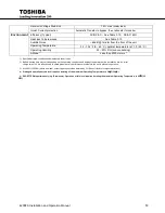
Page 51: ...nsing Altitude 3 Less than 2000 meters 3 1 Specified at rated conditions under balanced linear loads 2 Battery backup time may vary depending on the operating conditions and ambient temperature at the installation site An initial charge time of 24 hrs is necessary to obtain proper battery performance level before the unit is placed in operation 3 At 6600 ft 2000 m above sea level output capacity s...

Page 52: ... Float Charge Regulation 324 0 VDC 2 Ripple Voltage 0 5 V R M S Rated Back up Time 3 9 min at full load 4 min at full load Rated Charge Current 4 0 Amps Output Rated Voltage 208 120 VAC Rated Current 42 0 Amps 69 5 Amps Rated Power Factor 0 8 lagging Output Cables Required 3 phase 4 Wire GND Voltage Regulation phase phase 2 0 100 balanced load 3 0 100 unbalanced load Voltage Adjustment Range 5V Ma...

Page 53: ...ditions under balanced linear loads 2 Battery backup time may vary depending on the operating conditions and ambient temperature at the installation site An initial charge time of 24 hrs is necessary to obtain proper battery performance level before the unit is placed in operation 3 At 6600 ft 2000 m above sea level output capacity should be derated by 3 Consult factory for higher elevations 4 Pro...

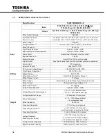
Page 54: ...um Harmonic Currents 1 Less than 8 5 1 Less than 5 5 1 Battery DC Nominal Voltage Range 288 VDC 216 332 VDC Float Charge Regulation 324 0 VDC 2 Ripple Voltage 0 5 V R M S Rated Back up Time 2 Refer to Battery System Manual 2 Rated Charge Current 10 0 Amps Output Rated Voltage Determined by Output Transformer internal to the unit Rated Current VA Nominal Output Voltage 1 73 Rated Power Factor 0 8 l...

Page 55: ...nsing Altitude 3 Less than 2000 meters 3 1 Specified at rated conditions under balanced linear loads 2 Battery backup time may vary depending on the operating conditions and ambient temperature at the installation site An initial charge time of 24 hrs is necessary to obtain proper battery performance level before the unit is placed in operation 3 At 6600 ft 2000 m above sea level output capacity s...

Page 56: ...1 Less than 3 THD 1 Battery DC Nominal Voltage Range 288 VDC 216 to 332 VDC Float Charge Regulation 324 0 VDC 2 Ripple Voltage 0 5 V R M S Rated Back up Time 2 Refer to Battery System Manual Rated Charge Current 10 0 Amps Output Rated Voltage 208 120 VAC Rated Current 83 4 Amps Rated Power Factor 0 8 lagging Output Cables Required 3 phase 4 Wire GND Voltage Regulation phase phase 2 0 100 balanced ...

Page 57: ...ing Altitude 3 Less than 6600 ft 2000 m 3 1 Specified at rated conditions under balanced linear loads 2 Battery backup time may vary depending on the operating conditions and ambient temperature at the installation site An initial charge time of 24 hrs is necessary to obtain proper battery performance level before the unit is placed in operation 3 At 6600 ft 2000 m above sea level output capacity ...

Page 58: ...ominal Voltage Range 288 VDC 216 to 332 VDC Float Charge Regulation 324 0 VDC 2 Ripple Voltage 0 5 V R M S Rated Back up Time 2 3 min at full load 2 Rated Charge Current 4 0 Amps Output Rated Voltage 208 120 VAC Rated Current 83 4 Amps Rated Power Factor 0 8 lagging Output Cables Required 3 phase 4 Wire GND Voltage Regulation phase phase 2 0 100 balanced load 3 0 100 unbalanced load Voltage Adjust...

Page 59: ...n 6600 ft 2000 m 3 1 Specified at rated conditions under balanced linear loads 2 Battery backup time may vary depending on the operating conditions and ambient temperature at the installation site An initial charge time of 24 hrs is necessary to obtain proper battery performance level before the unit is placed in operation 3 At 6600 ft 2000 m above sea level output capacity should be derated by 3 ...

Page 60: ...operation Current Limit 115 maximum Harmonic Currents 1 Less than 3 THD 1 Battery DC Nominal Voltage Range 288 VDC 216 to 332 VDC Float Charge Regulation 324 0 VDC 2 Ripple Voltage 0 5 V R M S Rated Back up Time 2 Refer to Battery System Manual 2 Rated Charge Current 10 0 Amps Output Rated Voltage Determined by Output Transformer internal to the unit Rated Current VA Nominal Output Voltage 1 73 Ra...

Page 61: ...y 30 90 RH non condensing Altitude 3 Less than 2000 meters 3 1 Specified at rated conditions under balanced linear loads 2 Battery backup time may vary depending on the operating conditions and ambient temperature at the installation site An initial charge time of 24 hrs is necessary to obtain proper battery performance level before the unit is placed in operation 3 At 6600 ft 2000 m above sea lev...

Page 62: ... Less than 3 THD 1 Battery DC Nominal Voltage Range 288 VDC 216 to 332 VDC Float Charge Regulation 324 0 VDC 2 Ripple Voltage 0 5 V R M S Rated Back up Time 2 Refer to Battery System Manual Rated Charge Current 11 5 Amps Output Rated Voltage 208 120 VAC Rated Current 138 9 Amps Rated Power Factor 0 8 lagging Output Cables Required 3 phase 4 Wire GND Voltage Regulation phase phase 2 0 100 balanced ...

Page 63: ...ng Altitude 3 Less than 2000 meters 3 1 Specified at rated conditions under balanced linear loads 2 Battery backup time may vary depending on the operating conditions and ambient temperature at the installation site An initial charge time of 24 hrs is necessary to obtain proper battery performance level before the unit is placed in operation 3 At 6600 ft 2000 m above sea level output capacity shou...

Page 64: ...nal Voltage Range 288 VDC 216 to 332 VDC Float Charge Regulation 324 0 VDC 2 Ripple Voltage 0 5 V R M S Rated Back up Time 2 4 5 min at full load 2 Rated Charge Current 11 5 Amps Output Rated Voltage 208 120 VAC Rated Current 138 9 Amps Rated Power Factor 0 8 lagging Output Cables Required 3 phase 4 Wire GND Voltage Regulation phase phase 2 0 100 balanced load 3 0 100 unbalanced load Voltage Adjus...

Page 65: ... 2000 meters 3 1 Specified at rated conditions under balanced linear loads 2 Battery backup time may vary depending on the operating conditions and ambient temperature at the installation site An initial charge time of 24 hrs is necessary to obtain proper battery performance level before the unit is placed in operation 3 At 6600 ft 2000 m above sea level output capacity should be derated by 3 Cons...

Page 66: ...c Currents 1 Less than 3 THD 1 Battery DC Nominal Voltage Range 288 VDC 216 to 332 VDC Float Charge Regulation 324 0 VDC 2 Ripple Voltage 0 5 V R M S Rated Back up Time 2 Refer to Battery System Manual 2 Rated Charge Current 11 5 Amps Output Rated Voltage Determined by Output Transformer internal to the unit Rated Current VA Nominal Output Voltage 1 73 Rated Power Factor 0 8 lagging Output Cables ...

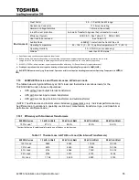
Page 67: ...perature to 90 F 32 C 5 SHORT TERM operation only e g Brownouts Operation at this level requires derating the maximum Operating Temperature to 95 F 35 C 4200FA Efficiencies and Thermal Losses at Various Loads 7 10 The tables below list typical efficiency at 100 load and thermal loss at various loads for the 15 25 30 50kVA units in three configurations UPS without input output internal transformers...

Page 68: ...50 7112 9915 16 802 50 Load 4403 5417 7857 13 878 25 Load 3449 4106 6430 8961 0 Load 2 730 4 077 4 892 6 403 7 10 4 Efficiency with Input and Output Transformer 4200FA Series 15 kVA w 2 Xfmr 25 kVA w 2 Xfmr 30 kVA w 2 Xfmr 50 kVA w 2 Xfmr 100 Load 85 1 86 7 85 1 85 8 Contact the factory for additional information on efficiency vs load curves 7 10 5 Thermal Loss in BTU Hr with Input and Output Tran...

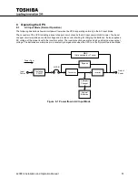
Page 69: ...ircuit maintains a constant voltage and provides current limiting for charging the batteries It also supplies a DC voltage of the proper level to the inverter section The inverter section generates a high quality sine wave output voltage The batteries are maintained in a constantly charged state when the UPS is in the Normal Operation Mode Figure 8 1 Power flow in AC Input Mode Converter Inverter ...

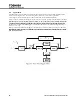
Page 70: ...ow will re transfer to the AC Input Mode Normal Operation automatically If the power flow is transferred to the Bypass circuit due to a fault condition then the power flow must be transferred manually from the UPS s Bypass circuit back to the Inverter circuit after repairing the fault see Start up Procedure If the power flow is transferred to the Bypass circuit due to an overload condition then th...

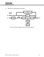
Page 71: ...ptional Alternate Input Models 8 3 Figure 8 3 Power flow in Bypass mode for the Alternate Input Models Power Flow Converter Inverter Bypass Charger Chopper Isolating XFMR External Batteries Output Power MCCB MBS Not available for LT units Input Power Bypass Power ...

Page 72: ...nverts hence Inverter the DC power into AC power The AC power is available at the output This back up process will continue until the battery voltage drops below a specific minimum level When this occurs the batteries will stop supplying power to the load This minimum level is the rated minimum voltage V min Figure 8 4 Power flow in battery backup mode Converter Inverter Bypass Charger Chopper Iso...

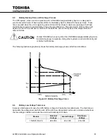
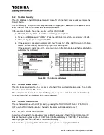
Page 73: ... of load temperature and other variables CAUTION Contact TOSHIBA when using other than TOSHIBA designed Battery Systems to determine proper compliance Using other systems could void Warranty and or Safety Certifications The following illustration graphically shows the battery discharge process at full load conditions Figure 8 5 Battery Discharge Curve Battery Low Voltage Tolerances 8 6 Excessive d...

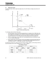
Page 74: ...ring safety and long battery life 2 Second constant voltage control starts and current gradually decreases as the batteries charge to their normal fully charged state 3 Third a slight trickle current continues to flow into the batteries to keep them fully charged and floating at the normal DC Voltage level A full recharge usually requires approximately 24 72 hours 90 recharge in 10 X discharge tim...

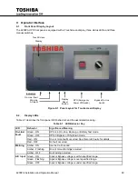
Page 75: ... mode Green OFF UPS in Bypass of Shutdown mode Red ON One or more faults occurred See Records Faults for details Red OFF No fault occurred Warning Amber ON Service Call needed Amber Flashing One or more Warnings occurred Amber OFF No Warning occurred A C Input Green ON Input or Bypass voltage is within specified range Green Flashing Input or Bypass voltage is over specified range Green OFF Input o...

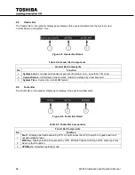
Page 76: ...iated by pressing the switch to the closed shutdown position The effect of using the EPO switch is the same whether the UPS is in the AC Input Mode Battery Backup Mode or the Bypass Mode See EMERGENCY OFF screen The following figure shows the UPS condition after application of the EPO switch Use the Start up Procedure for restarting the unit UPS Cabinet AC Output 3Ph 4W Static Switch Bypass AC Inp...

Page 77: ...m Functions 9 6 An audible alarm buzzer will sound when the UPS is in the battery backup mode has a fault has low battery voltage or is in an overload condition The buzzer will also beep each time an effective item is touched on the touchscreen The following chart shows the buzzer pattern durations for each condition Time units are shown in seconds Table 9 2 AUDIBLE ALARMS Condition Audible Patter...

Page 78: ...creen The buzzer can be silenced most easily by pressing the Buzzer Silent button on the Quick Access Toolbar Alternatively the buzzer can also be silenced by selecting the Settings tab and then set the Buzzer Silent parameter to Disable This will turn off the buzzer for the current alarm status but the buzzer will still sound when the next Fault Warning condition occurs The buzzer can be disabled...

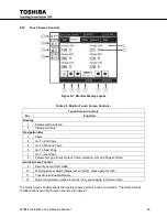
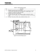
Page 79: ...ponents Initial Main Display Touchscreen Layout No Function 1 Quick Access Toolbar Interface Status Switches push button icon changes to reflect current status 2 Header Bar Displays system load status and time 3 Menu TABS Top level menu Touch a Tab to activate the display mode 3a Data display area 3b Update Displays current status and operation hints 4 Footer Bar Displays Faults Warnings and UPS O...

Page 80: ...tatus UPS status at the moment Status is delayed by a few seconds 3 System Time Current time in AM PM format Footer Bar 9 9 The Footer Bar on the graphic display panel displays three system parameters Figure 9 6 Footer Bar Detail Table 9 5 Footer Bar Components Footer Bar Components No Function 1 Fault Displays last fault sensed by UPS A Fault causes the UPS to switch to bypass and it will not aut...

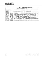
Page 81: ...Previous Page 6 Go To Next Page 7 Go To Last Page 8 Parameter Type Input Output Communication DC and Pages of Data Quick Access Toolbar 9 Security Level USR ADM 10 Warning Buzzer Switch Status press for ON press again for OFF 11 Touchscreen Enable Disable 12 Quick View Selector press for Quick View press again for Normal View The Quick Access Toolbar allows the operator easily perform routine comm...

Page 82: ... will sound again at next fault event To silence buzzer for all fault events set to Disable Touch Screen ON OFF button Press to toggle between ON and OFF ON enables all touchscreen active areas OFF disables all touchscreen areas except the TOUCH button Quick View On Off Selector Press to toggle between Normal view and Quick view Quick view displays a simultaneous summary of the Input Output Bypass...

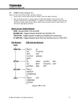
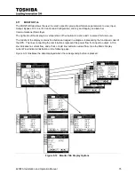
Page 83: ...allow immediate control of important functions Menu Tabs allow access to varying degrees of detailed information concerning the UPS operation performance and parameters The degree of information available is determined by the Security mode which can be changed pressing the top Quick Access Toolbar button and entering the appropriate password Figure 9 8 Menu Tree ...

Page 84: ... will return to the Main display and the Security button will display the USR level Figure 9 9 Changing Security Level Toolbar Buzzer ON OFF 9 13 The UPS Buzzer sounds when a fault occurs or when the UPS is switched to backup mode The Toolbar allows the user to turn on off the buzzer The buzzer can also be enabled or disabled through the setup menu If the Buzzer is disabled through the setup menu ...

Page 85: ...e LL Line to Neutral LN and Voltage as a of rated Voltage The highlighted icon indicates the voltage display mode 3 Displays output current for all three phases 4 Changes current display mode Press repeatedly to display alternately the current in Amps A or as a of rated current The highlighted icon indicates the current display mode 5 Displays DC Bus voltage Battery voltage and Battery discharge c...

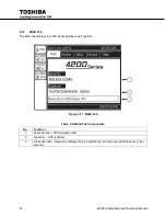
Page 86: ... tab displays the UPS Serial Number and Typeform Figure 9 11 MAIN Tab Table 9 9 MAIN Tab Components No Function 1 Serial Number UPS Serial Number 2 Typeform UPS typeform 3 Information Bar Randomly displays status helpful hints and acronym definitions every two seconds ...

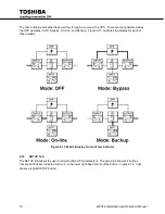
Page 87: ...ons 4 active and 1 reserved for future use The middle of the display contains five buttons arranged in a diagram representing the functional model of the UPS The lines connecting the mimic buttons represent the power flow from input to output A thin line indicates no current flow and a thick or bold line indicates current flow See the Mimic Display current Flow Indicator illustration on the follow...

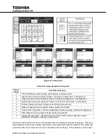
Page 88: ...ass On Line and Backup Figure 9 13 illustrates the display for each of these modes Figure 9 13 Mimic Display Current Flow Indicator SETUP Tab 9 18 The SETUP tab allows the user to adjust certain UPS parameters The setup tab shows 12 buttons Inactive buttons are indicated with a x in the lower right hand corner of the button Figure 9 14 right shows a typical SETUP button ...

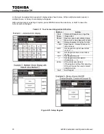
Page 89: ...nder Voltage Level Startup Voltage Level 5 Battery Voltage Current shutdown voltage battery test enable 6 Control and Configuration UPS time date status faults warnings password management 7 UPS Operation time Number of Faults Backup Operations 8 Display and Ext Comm Disp S W version buzzer status display calibration values RemotEye I P address data and network status Pressing an active button wil...

Page 90: ...ication Button Action Clear Delete all characters on input line Space Space Bar Recall Restores previously entered value Move cursor one space left or right DEL Delete character to right of cursor BS Back Space Delete character to left of cursor ABC Set Keypad to upper case letters A B C abc Set Keypad to lower case letters a b c 123 Set Keypad to write Set Keypad to write special characters Write...

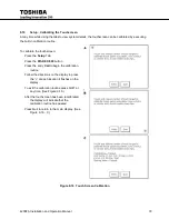
Page 91: ...etup Tab Press the DISP EX 800 button Press the entry Cali to begin the calibration routine Follow the directions on the display to press the at each location it flashes on the display To exit the calibration routine press QUIT at any time See Figure 9 16 After the touchscreen has been recalibrated the display will indicate that the calibration routine has passed Press Quit to return to the main d...

Page 92: ...RD Tab Description Backup Record Description Max Number of Records Operation Every change in operating mode is recorded by time date and mode 16 records before overwrite Backup Every time the UPS switches to and from backup the time and date are recorded 16 records before overwrite Fault Every time a fault occurs the date time and fault is recorded 16 records before overwrite ...

Page 93: ...auto page every 2 seconds The button will alternately blink in black on white white on black while in Auto Page mode Press the button again to exit Auto Page mode Figure 9 18 Help Index System Fault Messages 9 22 A Fault message is generated when either a fault condition occurs or a warning condition occurs three times within ten minutes The table below shows the possible fault messages and what a...

Page 94: ...ng If condition persists call for service DCUB DC bus unbalanced UPS is possibly faulty Check the UPS operation conditions at time of fault Not advisable to restart the UPS Call for service DCUVBS DC Bus Undervoltage during Boostup Mode DC Bus undervoltage condition occurred UPS is possibly faulty Check the UPS operation conditions at time of fault Not advisable to restart the UPS Call for service...

Page 95: ... unit is advised Have inspection service performed COV Charger Overvoltage Battery Charger not within specifications Contact the nearest Toshiba authorized representative for service CL Current Limit UPS not within specifications Contact the nearest Toshiba authorized representative for service EEUPDER EEPROM Update error Contact the nearest Toshiba authorized representative for service EE2RAER EE...

Page 96: ...is generated when the UPS changes operating mode The following tables list the possible operating modes for the UPS Table 9 15 System Mode Messages Display Meaning Backup Backup Power comes from other than input BattTest Battery Test Battery test in progress Bypass Bypass UPS is offline power is being provided directly from UPS input On Line On Line Input converter and inverter are running Double ...

Page 97: ... 90 or less during operation Continued operation in this mode will deplete battery and cause output shut down This can be adjusted by the operator Immediately shut down the load equipment in an orderly fashion and then press the STOP key LCRUN Local run command issued No action needed MANUAL UPS is in Manual mode No action needed OUT50HZ UPS set for 50 Hz Output No action needed PFAIL Input power ...

Page 98: ... the Setup tab ii Press System Date in the Data Display Area iii Enter the date in the following format Www Mmm DD YYYY a Www is the three character day of the week Mon Tue Wed b Mmm is the three character Month Jan Feb Mar c DD is the two digit day of the month 01 12 30 d YYYY is the four digit year 2013 iv Press Write to store the date v Press Quit to exit System Date setup 3 Enter the System Ti...

Page 99: ...has backup batteries verify the batteries are being charged Stopping the UPS 10 3 To stop the UPS rotate the Bypass On Line switch to Bypass The On Line LED changes from green to off The UPS is now in Bypass mode If the input breaker is turned off while UPS is in the bypass state the output power stops Any load devices will lose power Ensure that all sensitive loads have been previously shut down ...

Page 100: ...units are shown in seconds Table 10 1 AUDIBLE ALARMS Condition Audible Pattern Any Fault Intermittent buzz until fault clears Switch to Backup Single five second buzz Backup Operation Intermittent buzz once every ten seconds UPS Battery Shutdown Voltage Batt Voltage 79 Normal Warnings OL110 Overload Timer LB Low Battery Batt Voltage 90 Normal BLFN Battery Life Pre alarm Batt expires in 6 mo BLFE B...

Page 101: ...ow the power being routed through the MBS Heavy Line 5 Turn the Key Switch to RUN If parameter 527 Battery Test is set to Enable the UPS automatically performs a controlled system battery test Note The Automatic Battery Test is performed only when the software is enabled for this function The factory default is set to Disable Allow 24 72 hours for the batteries to fully charge Use the following pr...

Page 102: ... of the inverter halts Output power is now provided to the load through the unit s Bypass circuit While in this state of operation if a power failure occurs in the commercial power source the UPS will lose power Power to the critical load device will be interrupted The battery charging circuit and chopper circuit remains active DANGER Do not touch the UPS terminals even though the operation switch...

Page 103: ...pment attached to the UPS 10 9 2 Switch from UPS to Maintenance Bypass 1 Turn the BYPASS RUN key switch on the front panel to BYPASS Operation of the UPS inverter stops and the LED s display shows LED Light On Line Fault Off Warning Flashing A C Input Steady Green the system mode message left side of the touchscreen footer indicates the unit is in BYPASS Mode the system status message right side o...

Page 104: ...ates the unit is in BYPASS Mode the system status message right side of the touchscreen footer indicates the unit is in BYP Mode the LED s light as shown LED Light On Line Fault Off Warning Flashing A C Input Steady Green 3 For units with an external battery cabinet turn on MCCB BATTERY CABINET 4 Locate the large red maintenance bypass switch middle of inner front panel of the UPS EXCEPT for Base ...

Page 105: ...duced and the BYPASS RUN key switch is in the RUN position the UPS will automatically transfer to Bypass and the footer display will change to a System Fault Message UPSOL b System Warning Message OL110 c System Mode Message BYP 3 If the overload condition persists See Specifications the UPS will shut down a If in Online Mode the Unit will transfer to Bypass Mode b If in Bypass Mode the unit will ...

Page 106: ...rm Yes See Audible Alarm Functions Visible Alarm Red Fault LED illuminated Inverter OL No Fault Lamp Bypass OL Fault Lamp on Relay Contact Alarm Fault Relay closed Bypass Relay closed Inverter OL Bypass Relay closed Bypass OL Bypass Relay open and Fault relay closed Auto Retransfer No Inverter OL Yes if bypass ok Bypass OL No Protection Item Low Battery Voltage Level 1 Low Battery Voltage Level 2 ...

Page 107: ...ndition This is where the service technician checks the unit for physical damage and verifies the installation of the UPS electrically 2 Static Checks This step verifies the proper settings within the UPS logic 3 Wiring Check The wiring power cables between Utility Load and Other external components and the UPS 4 Wiring Check The wiring to power cables and from control wires the battery cabinet 5 ...

Page 108: ...electrolyte The charging voltage temperature performance and connection resistance must be monitored periodically Necessary corrective maintenance must be made in order to assure the UPS supplies safe reliable power These items affect the life of batteries so replacement should be once every 3 to 5 years as a minimum All of the batteries must be replaced at the same time to eliminate the possibili...

Page 109: ...4200FA Installation and Operation Manual 97 13 External Dimensions Shipping Dimensions Weights External Dimensions 13 1 13 1 1 Dimensions 15 25 30 kVA with Casters ...

Page 110: ...98 4200FA Installation and Operation Manual 36 3 in 922 mm ...

Page 111: ...4200FA Installation and Operation Manual 99 13 1 2 Dimensions 15 25 30 kVA without Casters 4 1 in 104 mm Floor to Conduit knockout plate ...

Page 112: ...100 4200FA Installation and Operation Manual 13 1 3 Dimensions 50kVA with casters 38 3 in 59 3 in 35 5 in 4 5 in 114 mm Floor to Conduit knockout plate ...

Page 113: ...4200FA Installation and Operation Manual 101 13 1 4 Dimensions 50kVA without Casters LT version does not have the middle C channel skid 4 9 in 125 mm Floor to Conduit knockout plate ...

Page 114: ...ernal Batt w Internal Input Iso Xfmr w Internal Input Iso Xfmr Internal Output Auto Xfmr 15 kVA 794 lb 360 kg 900 lb 408 kg 783 lb 355 kg 988 lb 448 kg 25 kVA 804 lb 365 kg 910 lb 413 kg 793 lb 360 kg 998 lb 453 kg 30 kVA 809 lb 415 kg 915 lb 415 kg 798 lb 364 kg 1003 lb 455 kg 50 kVA 1221 lb 554 kg 2548 lb 1156 kg 1581 lb 717 kg 1941 lb 880 kg Table 13 4 Weight of Base Units UPS Approximate Weigh...

Page 115: ...4200FA Installation and Operation Manual 103 APPENDIX A Seismic Anchorages ...

Page 116: ...104 4200FA Installation and Operation Manual ...

Page 117: ...4200FA Installation and Operation Manual 105 ...

Page 118: ...106 4200FA Installation and Operation Manual ...

Page 119: ...mil 8 Nominal battery voltage based on the use of VRLA type batteries is 2 0 volts cell VPC nominal 9 Maximum battery discharge current based on lowest permissible discharge voltage of 1 6 VPC 10 DC wires should be sized to allow not more than a 2 volt drop at maximum discharge current 11 Weights include internal batteries 12 Sizing calculations based on the following assumptions Not more than 3 c...

Page 120: ... Rating Feet 15 0 97 42 60 A 1 x 6 1 x 4 380 25 0 97 67 90 A 1 x 3 1 x 1 380 30 0 97 81 110 A 1 x 2 1 x 1 380 50 0 97 138 175 A 1 x 2 0 1 250 380 External Battery Input 288VDC Nominal Battery Capacity Required for Full Load Output Maximum Discharge at Full Load Output Suggested External Feeder Breaker Suggested Minimum Feeder Wire Size Per Phase Suggested Maximum Feeder Length For Min Wire Size in...

Page 121: ...sted External Feeder Breaker Suggested Minimum Feeder Wire Size Per Phase Neutral Suggested Maximum Feeder Length For Min Wire Size in Steel Conduit kVA Amps Amps AWG or kcmil at 75º C Temp Rating Feet 15 42 60 A 1 x 6 1 x 4 380 25 67 90 A 1 x 3 1 x 1 380 30 81 110 A 1 x 1 1 x 1 380 50 138 175 A 1 x 3 0 1 x 250 380 Battery Input 288VDC Nominal Battery Capacity Required for Full Load Output Maximum...

Page 122: ...g Feet 15 0 97 26 35 A 1 x 8 480 25 0 97 40 60 A 1 x 6 480 30 0 97 48 70 A 1 x 6 480 50 0 97 77 100 A 1 x 3 480 Battery Input 288VDC Nominal Battery Capacity Required for Full Load Output Maximum Discharge at Full Load Output Suggested External Feeder Breaker Suggested Minimum Feeder Wire Size Per Phase Suggested Maximum Feeder Length For Min Wire Size in Steel Conduit kWB Amps DC Amps AWG or kcmi...

Page 123: ...External Feeder Breaker Suggested Minimum Feeder Wire Size Per Phase Neutral Suggested Maximum Feeder Length For Min Wire Size in Steel Conduit kVA Amps Amps AWG or kcmil at 75º C Temp Rating Feet 15 42 60 A 1 x 6 1 x 4 380 25 69 90 A 1 x 3 1 x 1 380 30 83 110 A 1 x 2 1 x 1 380 50 139 175 A 1 x 2 0 1 x 250 380 Battery Input 288VDC Nominal Battery Capacity Required for Full Load Output Maximum Disc...

Page 124: ...and Suggested External Feeder Breaker Suggested Minimum Feeder Wire Size Per Phase Neutral Suggested Maximum Feeder Length For Min Wire Size in Steel Conduit kVA Amps Amps AWG or kcmil at 75º C Temp Rating Feet 15 21 30 A 1 x 10 1 x 12 480 25 32 50 A 1 x 8 1 x 6 480 30 38 60 A 1 x 6 1 x 4 480 50 61 80 A 1 x 4 1 x 2 480 Battery Input 288VDC Nominal Battery Capacity Required for Full Load Output Max...

Page 125: ...ing Feet 15 0 97 21 30A 1 x 10 480 25 0 97 32 45 A 1 x 8 480 30 0 97 38 60 A 1 x 8 480 50 0 97 61 80 A 1 x 4 480 Battery Input 288VDC Nominal Battery Capacity Required for Full Load Output Maximum Discharge at Full Load Output Suggested External Feeder Breaker Suggested Minimum Feeder Wire Size Per Phase Suggested Maximum Feeder Length For Min Wire Size in Steel Conduit kWB Amps DC Amps AWG or kcm...

Page 126: ...ternal Feeder Breaker Suggested Minimum Feeder Wire Size Per Phase Neutral Suggested Maximum Feeder Length For Min Wire Size in Steel Conduit kVA Amps Amps AWG or kcmil at 75º C Temp Rating Feet 15 42 60 A 1 x 6 1 x 4 480 25 69 90 A 1 x 3 1 x 1 480 30 83 110 A 1 x 2 1 x 1 480 50 139 175 A 1 x 2 0 1 x 250 480 Battery Input 288VDC Nominal Battery Capacity Required for Full Load Output Maximum Discha...

Page 127: ... Y 0 10 UPS Installation Date Installed Date R R W YYYYMMDD Y 1 1 Input Line to Line Voltage AB Voltage AB V R R Y 1 2 Input Line to Line Voltage BC Voltage BC V R R Y 1 3 Input Line to Line Voltage CA Voltage CA V R R Y 1 4 Input Line to Neutral Voltage AN Voltage AN V R R Y 1 5 Input Line to Neutral Voltage BN Voltage BN V R R Y 1 6 Input Line to Neutral Voltage CN Voltage CN V R R Y 1 7 Input P...

Page 128: ...nput Line R R Y 1 41 Rated Line to Line Input Voltage Rated Voltage L L V R R Y 1 42 Rated Line to Neutral Input Voltage Rated Voltage L N V R R Y 1 43 Rated Input Current Rated Current A R R Y 1 45 Rated Input Power W Rated Power W W R R Y 1 46 Rated Input Power VA Rated Power VA VA R R Y 1 47 VIUV Detection Level VIUV DeLevel R R Y 1 49 VIOV Detection Level VIOV DeLevel R R Y 1 58 Enable Phase C...

Page 129: ...ng to decimal points Y 2 13 Output Power W Total Power W Total kW R R Y 2 21 Output Voltage A Voltage A R R Percentage of Line to Line and Line to Neutral Voltage are the same Y 2 22 Output Voltage B Voltage B R R Percentage of Line to Line and Line to Neutral Voltage are the same Y 2 23 Output Voltage C Voltage C R R Percentage of Line to Line and Line to Neutral Voltage are the same Y 2 24 Outpu...

Page 130: ...age BN V R R Y 3 6 Bypass Line to Neutral Voltage CN Voltage CN V R R Y 3 10 Bypass Frequency A Freq A dHz R R 600 for 60 0 Hz 500 for 50 0 Hz UPS will send you one decimal point and format it according to decimal points Y 3 11 Bypass Frequency B Freq B dHz R R 600 for 60 0 Hz 500 for 50 0 Hz UPS will send you one decimal point and format it according to decimal points Y 3 12 Bypass Frequency C Fr...

Page 131: ...g Float Vdc R R W Y 5 22 Low Battery Detection Level Low Batt Level Vdc R R Y 5 24 Battery Shutdown Level Batt SDown Level Vdc R R Y 5 26 Manual Battery Test Manual Batt Test R W R W Enable Start Battery Test Disable No Action If battery test Pass Test No Message backup record will record successful batt test Fail Test Displays VBLO or VBSD message with warning LED and Buzzer N 5 27 Auto Battery T...

Page 132: ... UPS Time R R W Y 6 8 Current State Current State R R 0 Shutdown 1 Shutdown 2 Shutdown 3 Shutdown 4 Shutdown 5 Shutdown 6 Bypass 7 Bypass 8 Bypass 9 On Line 10 On Line 11 BackUp 12 CVCF 13 Bypass 14 Bypass 15 Bypass 16 Bypass 17 Bypass Y 6 11 Faults Faults R R Y 6 12 Warnings Warnings R R Y 6 13 UPS Status Comm UPS Status Comm R R Y 6 25 Service Port Baud Rate Srv Port Baud R R 0 9600 1 19200 2 38...

Page 133: ...er Start Inverter Start R R W Y 6 42 Remote Switch Remote Bypass Switch R W Y 6 67 Auto Transfer AutoXfer R R W 255 or 1 Enable 0 Disabled Y 7 1 System Operation Time System Op Time Sec R R Y 7 2 Inverter Op Time Inverter Op Time Sec R R Y 7 23 Total Backups Total Backups R R Y 7 25 Total Faults Total Faults R R Y 7 27 Total Operations Total Operations R R Y 8 1 Display Firmware Version DFW Ver R ...

Page 134: ...ht Status Sblight R R 0 Off 1 On N 8 7 Display Sleep Timer TMRsleep Min R W R W N 8 8 Buzzer Buzzer R W R W 0 Disable 1 Full Enable N 8 9 Buzzer Status Sbuzzer R R 0 Off 1 Idle 2 Alarm Sounding 3 Alarm Silenced Y 8 11 Display Calibration Cali Disp R W R W 0 Disabled 255 Enabled Note Only display can write Others read only N 8 21 User Interface Tone UI Tone R W R W N 8 25 Wled Blink BK Warning Led ...

Page 135: ...etwork Mask Address REye Mask IP R W R W Ex 255 0 0 0 Note Only RemoteEye III can write Others read only Y 8 54 RemotEye Gateway Address REye Gway IP R W R W Ex 10 128 33 1 Note Only RemoteEye III can write Others read only Y 8 55 RemotEye Installation Status Sreye R W R W Note Only RemoteEye III can write Others read only Y 8 57 RemotEye Data Link Status Sreye Datlink R W R W 0 Unknown 1 Link Dow...

Page 136: ...124 4200FA Installation and Operation Manual ...

Page 137: ......

Page 138: ...INDUSTRIAL DIVISION 13131 West Little York Rd Houston TX 77041 Tel 713 466 0277 Fax 713 466 8773 US 877 867 8773 Canada 800 872 2192 Mexico 01 800 527 1204 www toshiba com ind Printed in the U S A ...

Reviews: