
4200FA Installation and Operation Manual
95
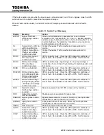
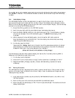
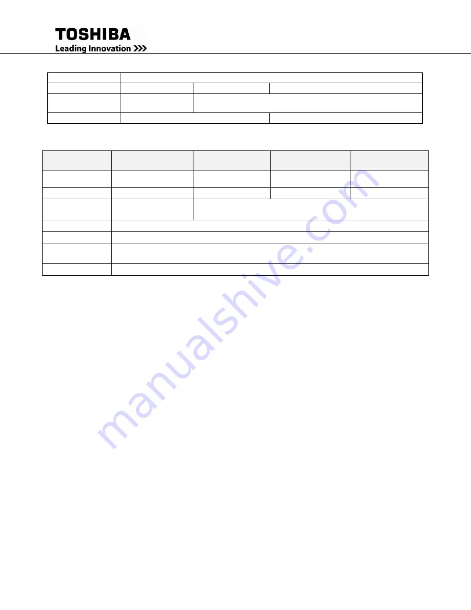
Audible Alarm
Yes: See Audible Alarm Functions
Visible Alarm
NO
NO
NO
Relay Contact
Alarm
Low Battery Relay
closed
Bypass Relay closed
Auto-Retransfer
No
Yes, if bypass ok
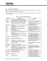
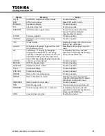
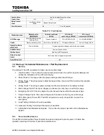
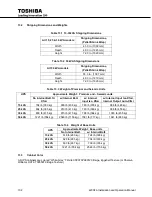
Table 11.2 Fault Alarms
Protection Item
Memory error
(EE2RAER)
Internal overheat
(DOH)
DC circuit
overvoltage (DCOV)
DC circuit
overcurrent (DCOC)
LCD Message
MAIN EEPROM to ROM
Loading Error
Device Overheat
DC OVERVOLTAGE
DC OVERCURRENT
Cause
Display board chip error
Fan failure; high ambient
Chopper malfunction
Inverter / chopper fault
Operation Mode
after Fault
Start is inhibited
Bypass operation; chopper and inverter are stopped
Audible Alarm
Yes; continuous buzzer
Visible Alarm
Red Fault LED illuminated
Relay Contact
Alarm
Fault relay closed; bypass relay closed
Auto-Retransfer
NO
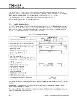
12 Start-up / Scheduled Maintenance / Part Replacement
Start-up
12.1
The startup of the UPS equipment is broken up into several steps:
1. Initial Condition: This is where the service technician checks the unit for physical damage and
verifies the installation of the UPS (electrically).
2. Static Checks: This step verifies the proper settings within the UPS logic.
3. Wiring Check: The wiring (power cables) between Utility, Load, and Other external components
and the UPS.
4. Wiring Check: The wiring to (power cables) and from (control wires) the battery cabinet.
5. Main Voltage Check: The input voltages are checked to verify they are within the range.
6. Energizing the UPS: This step begins the internal self-checks within the processor logic.
7. Output Voltage Check: The output voltages are checked to verify they are within range.
8. EPO (Emergency Power Off): The EPO is operated to verify its operation in case of an
emergency.
9. Load Testing: Performed if load is available.
10. Generator Testing: Performed if Generator is available.
11. Internal/External Maintenance Bypass: This verifies the proper operation of the Maintenance
Bypass.
Preventive Maintenance
12.2
The 4200
FA
Uninterruptible Power Systems have been designed to provide years of trouble-free
operation requiring a minimum of preventive maintenance.
Summary of Contents for 4200FA Series
Page 2: ...4200FA Installation and Operation Manual ...
Page 12: ...vi 4200FA Installation and Operation Manual ...
Page 16: ...4 4200FA Installation and Operation Manual NOTE This Label for Battery Units Only ...
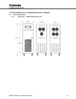
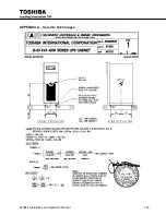
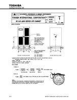
Page 110: ...98 4200FA Installation and Operation Manual 36 3 in 922 mm ...
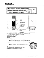
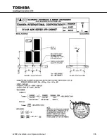
Page 115: ...4200FA Installation and Operation Manual 103 APPENDIX A Seismic Anchorages ...
Page 116: ...104 4200FA Installation and Operation Manual ...
Page 117: ...4200FA Installation and Operation Manual 105 ...
Page 118: ...106 4200FA Installation and Operation Manual ...
Page 136: ...124 4200FA Installation and Operation Manual ...
Page 137: ......


