


4
Toshiba 1110651160 (EN)
520 mm
420 mm
43
m
m
80
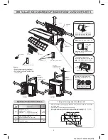
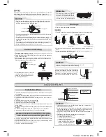
How to remove the drain cap
Clip the drain cap by needle-nose
pliers and pull out.
How to remove the drain hose
•
The drain hose can be removed by removing the
screw securing the drain hose and then pulling out
the drain hose.
•
When removing the drain hose, be careful of any
sharp edges of steel plate. The edges can injuries.
•
To install the drain hose, insert the drain hose
fi rmly until the connection part contacts with heat
insulator, and the secure it with original screw.
How to fi x the drain cap
1) Insert hexagon
wrench (4 mm)
in a center head.
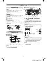
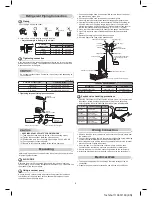
In case of right or left piping
•
After scribing slits of the front panel
with a knife or a making-off pin,
cut them with a pair of nippers or
an equivalent tool.
In case of bottom right or bottom left piping
•
After scribing slits of the front panel
with a knife or a making-off pin,
cut them with a pair of nippers or
an equivalent tool.
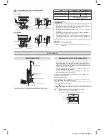
Liquid side
Gas side
(To the forefront of fl are)
Outward form of indoor unit
R 30 mm (Use polisin (polyethylene)
core or the like for bending pipe.)
Use the handle of screwdriver, etc.
Heat insulator
Drain hose
4 mm
Do not apply lubricating oil
(refrigerant machine oil) when
inserting the drain cap. Application
causes deterioration and drain
leakage from the plug.
Slit
Slit
1. Die-cutting front panel slit
Cut out the slit on the leftward or right side of the front panel for the left
or right connection and the slit on the bottom left or right side of the front
panel for the bottom left or right connection with a pair of nippers.
2. Changing drain hose
For leftward connection, bottom-leftward connection and rearleftward
connection’s piping, it is necessary to change the drain hose and drain
cap.
) Firmly insert the drain cap.
No gap
CAUTION
Firmly insert the drain hose and drain cap; otherwise, water may leak.
Left-hand connection with piping
•
Bend the connecting pipe so that it is laid within 43 mm above the wall
surface. If the connecting pipe is laid exceeding 43 mm above the wall
surface, the indoor unit may unstably be set on the wall.
When bending the connecting pipe, make sure to use a spring bender so as
not to crush the pipe.
Bend the connecting pipe within a radius of 30 mm.
To connect the pipe after installation of the unit (fi gure)
Insert a hexagon
wrench (4 mm).
Piping and Drain Hose Installation
* Since dewing results in a machine trouble, make sure to insulate both
connecting pipes. (Use polyethylene foam as insulating material.)
Piping and drain hose forming
How to install the air inlet grille on the indoor unit
•
When attaching the air inlet grille,
perform the same process as for
removal but in reverse order.
Wiring Connection
How to connect the connecting cable
Wiring of the connecting cable can be carried out without removing
the front panel.
1. Remove the air inlet grille.
Open the air inlet grille upward and pull it toward you.
. Remove the terminal cover and cord clamp.
3. Insert the connecting cable (according to the local rule) into the pipe hole
on the wall.
4. Take out the connecting cable through the cable slot on the rear panel so
that it protrudes about 15 cm from the front.
5. Insert the connecting cable fully into the terminal block and secure it
tightly with screws.
6. Tightening torque : 1. N·m (0.1 kgf·m)
7. Secure the connecting cable with the cord clamp.
8. Fix the terminal cover, rear plate bushing and air inlet grille on the indoor
unit.
1 2 3
110 mm
20 mm
10 mm
80 mm
Earth line
about 15 cm
Rear right
Rear left
Bottom left
Left
Bottom right
Right
Di
e-
cu
tti
ng
fro
nt
p
an
el
s
lit
Ch
an
gi
ng
dr
ai
n
ho
se
Pi
pi
ng
p
re
pa
ra
tio
n
CAUTION
•
Be sure to refer to the wiring system diagram labeled inside the front
panel.
•
Check local electrical cords and also any specifi c wiring instructions or
limitations.
NOTE
•
Use stranded wire only.
•
Wire type : H07RN-F or more
Screw
Terminal cover
Terminal block
Cord clamp
Screw
Earth line
Connecting cable
Connecting cable
Stripping length of the connecting cable