


Toshiba 1110651160 (EN)
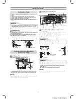
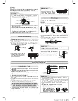
Shield pipe
Air filter
Hook
Hook
170 mm or more
50 mm or more
170 mm or more
1
Installation
plate
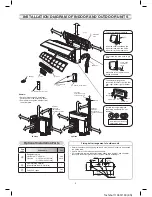
INSTALLATION DIAGRAM OF INDOOR AND OUTDOOR UNITS
Part
code
Parts name
Q’ty
A
Refrigerant piping
Liquid side :
∅
6.35 mm
Gas side :
∅
1.70 mm (18 Class)
:
∅
15.88 mm (4 Class)
One
each
B
Pipe insulating material
(polyethylene foam, 8 mm thick)
1
C
Putty, PVC tapes
One
each
Optional Installation Parts
•
Secure the outdoor unit with fixing bolts and nuts if the unit is likely to be exposed
to a strong wind.
•
Use
∅
8 mm or
∅
10 mm anchor bolts and nuts.
•
If it is necessary to drain the defrost water, attach drain nipple
9
and cap water
proof
!
to the bottom plate of the outdoor unit before installing it.
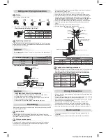
Fixing bolt arrangement of outdoor unit
Wall
(Attach to the front panel.)
For the rear left and left piping
Insert the cushion between the
indoor unit and wall, and tilt the
indoor unit for better operation.
Do not allow the drain hose to get
slack.
Make sure to run the drain hose
sloped downward.
Cut the piping
hole sloped
slightly.
The auxiliary piping can be
connected to the left, rear left, rear
right, right, bottom right or bottom
left.
Right
Rear right
Left
Bottom right
Rear
left
Bottom left
Insulate the refrigerant pipes
separately with insulation, not
together.
8 mm thick heat resisting
polyethylene foam
8
Pan head wood
screw
3
Batteries
2
Wireless remote control
4
Remote control holder
6
Filter
5
Filter
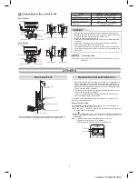
108 mm
600 mm
28 mm
25 mm
90 mm
125 mm
320 mm
86 mm
102 mm
Air outlet
Drain outlet
Air inlet
Vinyl tape
Apply after carrying
out a drainage test.
Saddle
Extension
drain hose
(Not available,
provided by installer)
100 mm or more
100 mm or more
600 mm or more
600 mm or more
100 mm or more
600 mm or more
600 mm or more
600 mm or more
600 mm or more
100 mm or more
Extension
drain hose
(Not available,
provided by installer)
18 Class
24 Class
Remark :
•
Detail of accessory and installation
parts can see in the accessory sheet.
•
Some pictures might be different from
the actual parts.