


1
Toshiba 1110651160 (EN)
PRECAUTIONS FOR SAFETY
•
Before installation, please read these precautions for safety carefully.
•
Be sure to follow the precautions provided here to avoid safety risks. The symbols and their meanings are shown below.
WARNING
: It indicates that incorrect use of this unit may cause severe injury or death.
CAUTION
: It indicates that incorrect use of this unit may cause personal injury (*1), or property damage (*).
*1 : Personal injury means a slight accident, burn, or electrical shock which does not require admission or repeated hospital treatment.
* : Property damage means greater damage which affects assets or resources.
For general public use
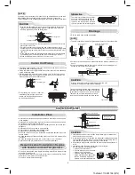
Power supply cord of parts of appliance for outdoor use shall be at least polychloroprene sheathed fl exible cord (design H07RN-F) or cord designation
6045 IEC66, 4.0 mm
or more and 1.5 mm
or more for connecting cable
(Shall be installed in accordance with national regulations).
To disconnect the appliance from the main power supply
CAUTION
This appliance must be connected to the main power supply by means of a circuit breaker or a switch with a contact separation of at least 3 mm in
all poles. If this is not possible, a power supply plug with earth must be used. This plug must be easily accessible after installation. The plug must be
disconnected from the power supply socket in order to disconnect the appliance completely from the mains.
DANGER
•
FOR USE BY QUALIFIED PERSONS ONLY.
•
TURN OFF MAIN POWER SUPPLY BEFORE ATTEMPTING ANY ELECTRICAL WORK. MAKE SURE ALL POWER SWITCHES ARE OFF.
FAILURE TO DO SO MAY CAUSE ELECTRIC SHOCK.
•
CONNECT THE CONNECTING CABLE CORRECTLY. IF THE CONNECTING CABLE IS CONNECTED WRONGLY, ELECTRIC PARTS MAY BE
DAMAGED.
•
CHECK THE EARTH WIRE THAT IT IS NOT BROKEN OR DISCONNECTED BEFORE INSTALLATION.
•
DO NOT INSTALL NEAR CONCENTRATIONS OF COMBUSTIBLE GAS OR GAS VAPORS.
FAILURE TO FOLLOW THIS INSTRUCTION CAN RESULT IN FIRE OR EXPLOSION.
•
TO PREVENT OVERHEATING THE INDOOR UNIT AND CAUSING A FIRE HAZARD, PLACE THE UNIT WELL AWAY (MORE THAN M) FROM
HEAT SOURCES SUCH AS RADIATORS, HEATERS, FURNACE, STOVES, ETC.
•
WHEN MOVING THE AIR CONDITIONER FOR INSTALLING IT IN ANOTHER PLACE AGAIN, BE VERY CAREFUL NOT TO GET THE SPECIFIED
REFRIGERANT (R) WITH ANY OTHER GASEOUS BODY INTO THE REFRIGERATION CYCLE. IF AIR OR ANY OTHER GAS IS MIXED IN THE
REFRIGERANT, THE GAS PRESSURE IN THE REFRIGERATION CYCLE BECOMES ABNORMALLY HIGH AND IT RESULTINGLY CAUSES
BURST OF THE PIPE AND INJURIES ON PERSONS.
•
IN THE EVENT THAT THE REFRIGERANT GAS LEAKS OUT OF THE PIPE DURING THE INSTALLATION WORK, IMMEDIATELY LET FRESH AIR
INTO THE ROOM. IF THE REFRIGERANT GAS IS HEATED BY FIRE OR SOMETHING ELSE, IT CAUSES GENERATION OF POISONOUS GAS.
WARNING
•
Never modify this unit by removing any of the safety guards or bypassing any of the safety interlock switches.
•
Do not install in a place which cannot bear the weight of the unit.
Personal injury and property damage can result if the unit falls.
•
Before doing the electrical work, attach an approved plug to the power supply cord.
Also, make sure the equipment is properly earthed.
•
Appliance shall be installed in accordance with national wiring regulations.
If you detect any damage, do not install the unit. Contact your TOSHIBA dealer immediately.
CAUTION
•
Exposure of unit to water or other moisture before installation could result in electric shock.
Do not store it in a wet basement or expose to rain or water.
•
After unpacking the unit, examine it carefully for possible damage.
•
Do not install in a place that can increase the vibration of the unit. Do not install in a place that can amplify the noise level of the unit or where noise and
discharged air might disturb neighbors.
•
To avoid personal injury, be careful when handling parts with sharp edges.
•
Please read this installation manual carefully before installing the unit. It contains further important instructions for proper installation.
REQUIREMENT OF REPORT TO THE LOCAL POWER SUPPLIER
Please make absolutely sure that the installation of this appliance is reported to the local power supplier before installation. If you experience any
problems or if the installation is not accepted by the supplier, the service agency will take adequate countermeasures.