


TOSHIBA
23
Operating the UPS
Operation Modes (Cont'd)
Battery Backup Mode
The following illustration shows power flow during the battery backup mode. When
commercial ac power failures occur, the UPS's batteries instantly begin supplying dc
voltage to the UPS's main inverter circuit. This circuit changes (inverts) the dc power into
ac power. The ac power is available at the unit's output. This back-up process will continue
until the UPS's battery voltage drops below a specific minimum level. When this occurs,
the batteries will stop supplying power to the load. This minimum level is the rated minimum
voltage (Vmin). The rated battery voltage chart on page 20 shows (Vmin). The battery
backup time and discharge process is explained on page 20.
Inverter
Power flow
Power flow in battery backup mode for the 2.4, 3.6, 6, and 8 kVA Models
Surge
absorber
Rectifier/
charger/
chopper
Line
filter
Input
power
MCCB
*Static
switch
Batteries
* Switches are
solid state devices
Output
power
Bypass
Line
filter
EPO (Emergency Power Off) Function
These units are equipped with terminals for receiving an emergency power-off (EPO) "closed
contact" switch command from a remote location (see 'terminal block details' on page 13 and terminal
block location on page 44). This safety feature enables quick shut-down of the UPS's ac output and
battery circuits. Usually the emergency power off switch is installed in a central location that is easily
accessible to personnel concerned with the operation of the UPS unit and the load equipment
connected to it. The EPO function is initiated by pressing the switch to the closed "shutdown" position.
The effect of using the EPO switch is the same whether the UPS unit is in the ac input mode (see page
22), battery backup mode (see page 23), or the circuit bypass mode (see page 22). The following figure
shows the UPS condition after application of the EPO switch.
MCCB
Rectifier/
charger/
chopper
Inverter
*Static
switch
Line
filter
Surge
absorber
Bypass
Power flow
TRIPPED
OFF
OFF
Output
power
(off)
Input
power
_
+
Batteries
* Switches are
solid state devices
Isolation
Transformer
(optional)
Line
filter
Isolation
Transformer
(optional)
Input
fuses
Output
fuses
Input
fuses
Output
fuses
_
+
General Safety
Inspections & Precautions
Connections
Equipment
Equipment
Specifications
Operating
Display Screens
Manual Run/Stop
Protection System
Maintenance & Options
Dimensions &
Weights
Index
Reference
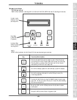
Equipment
Key Functions
Panel Layout &


