


16
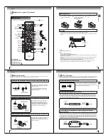
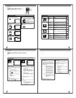
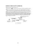
Connections
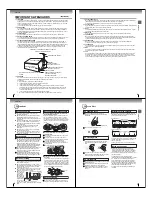
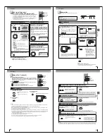
To playback from the VCR, connect the VCR to the TV/DVD as shown.
Select the “VIDEO2” by pressing
INPUT SELECT
repeatedly.
You can enjoy playing a TV game on the screen by adjusting to suitable brightness for your eyes.
1. Connect a TV Game to the TV/DVD.
2. Select the “GAME” by pressing
GAME
.
The GAME mode screen appears.
• This TV/DVD has the GAME mode function (see page 24).
Camcorder
To Audio/Video OUT
Audio/Video cable (not supplied)
Left side (LINE 2 IN)
Audio/Video cable (not supplied)
To Audio/Video OUT
INPUT SELECT
GAME
Connecting to a VCR
Connecting to a TV Game
Connecting to optional equipment
You can enjoy VCR, camcorder or TV game with connection to external
input.
Notes:
• You can also change the TV screen to the desired mode by pressing the CH +/– buttons.
• The TV/DVD can also be used as a display device for many video games. However, due to the wide variety of different types of signal
generated by these devices and subsequent hook-up variations required, they have not all been included in the suggested connection
diagrams. You’ll need to consult each component’s Owner’s Manual for additional information.
• Interactive video games that involve shooting a “gun” type of joystick at on-screen target may not work on this TV/DVD.
: Signal ow
: Signal ow
: Signal ow
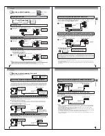
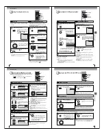
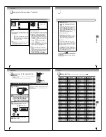
Using the audio/video inputs
Press
INPUT SELECT
repeatedly to select the desired mode.
“VIDEO1”, “VIDEO2”, “ColorStream” or TV channel will display on the screen for 4 seconds.
Note:
This key will not operate in DVD mode.
VIDEO1
To Audio/Video OUT
(yellow)
(red)
(white)
Audio/Video cable (not supplied)
VCR
(yellow)
(red)
(white)
(yellow)
(red)
(white)
TV Channel
VIDEO1
(Rear lower left)
VIDEO2
ColorStream
(Left side)
To AUDIO(L/R)/VIDEO IN
To AUDIO(L/R)/VIDEO IN
To AUDIO(L/R)/VIDEO IN
Note:
Picture might be muted for some VCR playback. This is not a malfunction of this unit.
To playback from the camcorder, connect the camcorder to the TV/DVD as shown.
Select the “VIDEO2” by pressing
INPUT SELECT
repeatedly.
Connecting to a camcorder
The LINE 1 IN
terminals can be used
in the same way.
Left side (LINE 2 IN)
Left side (LINE 2 IN)
The LINE 1 IN
terminals can be used
in the same way.
Only the LINE 2
IN terminals can
be used with the
GAME mode.
J5X00401A(Eng).indb 16
3/5/2550 12:11:10
17
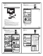
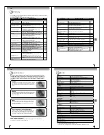
Connections
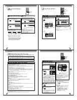
Connecting to an optional equipment with S-video output
If you connect a VCR with an S-VIDEO cable to the S-VIDEO IN jack on the left side of the TV/DVD, you must
also connect the audio cables to the AUDIO IN (LINE 2 IN) jacks on the left side of the TV/DVD. The S-VIDEO
cable only carries the video signal. The audio signal is separate.
Select the “VIDEO2” by pressing
INPUT SELECT
repeatedly.
Note:
When the S-VIDEO cable and the standard video cable are connected at the same time, the S-video cable takes precedence.
Left side (LINE 2 IN)
Ex. VCR with S-Video
To S-VIDEO OUT
To Audio (L/R) OUT
To S-VIDEO IN
Audio cable (not supplied)
S-Video cable (not supplied)
Connecting an optional equipment with ColorStream
®
(Component video) output
Your TV/DVD is capable of using ColorStream
®
(component video). Connecting your TV/DVD to a component
video compatible DVD player, such as a Toshiba DVD player with ColorStream
®
can greatly enhance picture
quality and performance.
The ColorStream
®
inputs on this unit are for use with devices that output 480i interlaced signals and 480p progressive signals.
This unit will not accept or display 720p progressive scan signals or 1080i interlaced high-de nition signals. If you connect a high-
de nition set-top receiver, 720p progressive scan DVD player, or other similar device to the unit’s ColorStream
®
inputs, YOU MUST
SWITCH THE DEVICE’S OUTPUT TO 480i INTERLACED OR 480p PROGRESSIVE MODE FIRST. Failure to do this will cause a
poor or no picture to display.
Rear lower right of the TV
Ex. DVD player with Component video
Audio cable (not supplied)
Component video cable (not supplied)
To Audio OUT
To Component
Video OUT
To AUDIO (L/R) IN
To COMPONENT
(Y, P
B
, P
R
) IN
Q
Selecting Component input mode
Press
INPUT SELECT
repeatedly to
select “ColorStream” mode.
When using the Component video cable,
an Audio cable must be connected to
AUDIO IN (L/R) (LINE 1 IN) jacks.
ColorStream
Notes:
•
Refer to the owner’s manual of the connected equipment as well.
•
When you connect the unit to other equipment, be sure to turn off the power and unplug all of the equipment from the wall outlet
before making any connections.
•
If you place the unit near a tuner or radio, the radio broadcast sound might be distorted. In this case, place the unit away from the
tuner and radio.
: Signal ow
: Signal ow
(playback)
(red)
(white)
To AUDIO (L/R) IN
J5X00401A(Eng).indb 17
3/5/2550 12:11:11
18
Connections
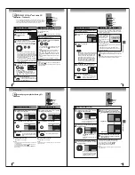
: Front speaker
: Rear speaker
: Sub woofer
: Center speaker
: Signal ow
Dolby Digital
Dolby Digital is the surround sound technology used in theaters showing the latest movies, and is now available to reproduce
this realistic effect in the home. You can enjoy motion picture and live concert DVD video discs encoded via the Dolby Digital
recording system with this dynamic realistic sound by connecting the TV/DVD to a 6 channel ampli er equipped with a Dolby
Digital decoder or Dolby Digital processor. If you have a Dolby Surround Pro Logic decoder, you will obtain the full bene t of
Pro Logic from the same DVD movies that provide full 5.1-channel Dolby Digital soundtracks, as well as from titles with the
Dolby Surround mark.
Connecting to an ampli er equipped with a Dolby
®
Digital decoder
Manufactured under license
from Dolby Laboratories.
Dolby, and the double-D
symbol are trademarks of
Dolby Laboratories.
Ampli er equipped with a
Dolby Digital decoder
To COAXIAL
type digital
audio input
75
:
coaxial cable (not supplied)
Dolby Surround
Pro Logic
You can enjoy the dynamic realistic sound of Dolby Surround Pro Logic by connecting an ampli er and speaker system (right and
left front speakers, a center speaker, and one or two rear speakers).
Q
With an ampli er equipped with a Dolby Digital
Connect the equipment the same way as described in “Connecting to an ampli er equipped with a Dolby Digital decoder.”
Refer to that ampli er’s owner’s manual and set the ampli er so that you can enjoy Dolby Surround Pro Logic sound.
Q
With an ampli er not equipped with a Dolby Digital
Connect the equipment as follows.
• This connection is only suitable for Video CDs and Audio CDs.
Ampli er equipped with a
Dolby Surround Pro Logic
* Connect one or two rear
speakers. The output sound
from the rear speakers will be
monaural even if you connect
two rear speakers.
Connecting to an ampli er equipped with a DTS
®
decoder
Digital Theater Systems (DTS)
DTS is a high quality surround technology used in theaters and now available for home use, on DVD video discs or audio CDs.
If you have a DTS decoder or processor, you can obtain the full bene t of 5.1 channel DTS encoded sound tracks on DVD
video discs or audio CDs.
“DTS” and “DTS Digital Out”
are registered trademarks of
DTS, Inc.
Ampli er equipped with
a DTS decoder
To COAXIAL
type digital
audio input
75
:
coaxial cable (not supplied)
To COAXIAL
type digital
audio input
*
75
:
coaxial cable (not supplied)
Connecting to an ampli er equipped with a Dolby Surround Pro Logic
* This section uses the following reference mark.
Rear lower left of the TV
Rear lower left of the TV
Rear lower left of the TV
To COAXIAL DIGITAL
AUDIO OUT
To COAXIAL DIGITAL
AUDIO OUT
To COAXIAL DIGITAL
AUDIO OUT
Connecting to optional equipment (Continued)
You can enjoy high quality dynamic sounds by connecting the
TV/DVD to optional audio equipment.
J5X00401A(Eng).indb 18
3/5/2550 12:11:11
19
Connections
MPEG2 sound
You can enjoy motion picture and live concert DVD video discs encoded via the MPEG2 recording system with dynamic
realistic sound by connecting an ampli er equipped with an MPEG2 audio decoder or MPEG2 audio processor.
Connecting to an ampli er equipped with an MPEG audio decoder
Connecting to an ampli er equipped with a digital audio input
2 channel digital stereo
You can enjoy the dynamic sound of 2 channel digital stereo by connecting an ampli er equipped with a digital audio input and
speaker system (right and left front speakers).
Note:
PCM audio is limited to DVD or CD playback.
Notes:
• DO NOT connect the COAXIAL DIGITAL AUDIO OUT jack of the TV/DVD to the AC-3 RF input of a Dolby Digital Receiver.
This input on your A/V Receiver is reserved for Laserdisc use only and is incompatible with the COAXIAL DIGITAL AUDIO
OUT jack of the TV/DVD.
• Connect the COAXIAL DIGITAL AUDIO OUT jack of the TV/DVD to the “COAXIAL” input of a Receiver or Processor.
• Refer to the owner’s manual of the connected equipment as well.
• When you connect the TV/DVD to other equipment, be sure to turn off the power and unplug all of the equipment from the
wall outlet before making any connections.
• The output sound of the TV/DVD has a wide dynamic range. Be sure to adjust the receiver’s volume to a moderate listening
level. Otherwise, the speakers and your hearing may be damaged by a sudden high volume sound.
• Turn off the ampli er before you connect or disconnect the TV/DVD’s power cord. If you leave the ampli er’s power on, the
speakers may be damaged.
Ampli er equipped with an
MPEG2 audio decoder
To COAXIAL
type digital
audio input
75
:
coaxial cable (not supplied)
Ampli er equipped with a
Digital audio input
To COAXIAL
type digital
audio input
75
:
coaxial cable (not supplied)
Rear lower left of the TV
Rear lower left of the TV
To COAXIAL DIGITAL
AUDIO OUT
To COAXIAL DIGITAL
AUDIO OUT
J5X00401A(Eng).indb 19
3/5/2550 12:11:12