


TOSHIBA
5.0
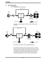
Operating the UPS
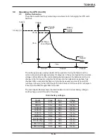
5.2
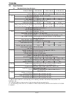
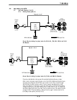
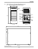
System Protection Features
The schematic shown below depicts the electrical locations of the protection devices
on the 500, 600, 750, 800, 1000, and 1200 VA UPS models.
5 - 4
Fuse
Over-
current
5-15R
UPS
receptacles
(rear panel)
Overheating
Capacitor
Capacitor
IGBT
IGBT
Bypass
Capacitor
IGBT
IGBT
Over-
current
Capacitor
UPS
receptacles
(rear panel)
IGBT
IGBT
Battery
Fuse
Power
input
plug
5-15P
+
-
Power
input
plug
5-20P
-
Battery
+
Bypass
Circuit
breaker
IGBT
IGBT
Current limit
Overload
Overvoltage
Undervoltage
Overheating
Overvoltage
Undervoltage
5-15R
Current limit
Overload
Input
abnormal
Low
battery
level
Input
abnormal
Low battery
level
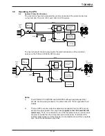
Notes:
1)
The UPS's RECT/CHOPPER and INVERTER, although separate electrical
circuits, are physically located on the same heat sink. This is applicable to all
models.
2)
The two UPS rear panel output receptacles are supplied from the UPS inverter
section through separate 15A output fuses (
applies to the 1500 and 2000 VA
model only
). Thus, an overload on one of the receptacle sets can cause a loss
of power to it while the other receptacle set remains active. If all of the UPS
indicator lights appear normal and power is not available at one of the receptacle
sets, check the associated output fuse.
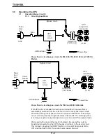
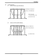
The next schematic shown below depicts the electrical locations of the protection
devices on the 1500 and 2000 VA UPS models.
Summary of Contents for 1400 Plus Series
Page 2: ...iii WARRENTY CARD INSERT ...
Page 3: ...iv WARRENTY CARD INSERT ...