


TOSHIBA
5.0
Operating the UPS
5.1
Operation Modes
5.1.1
AC Input Mode (normal operation)
5 - 1
UPS batteries
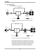
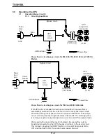
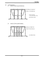
Power flow in AC input mode for 500, 600, 750, 800, 1000, and 1200
VA Models
Bypass circuit
UPS
circuit
(rear panel)
receptacles
UPS
= power flow
main
_
5-15P
5-15R
plug
input
Power
Fuse
Output Xfmr
+
(Plus Series)
UPS batteries
= power flow
Fuse
5-15R
Bypass circuit
UPS
receptacles
(rear panel)
Circuit
breaker
Power
input
plug
5-20P
UPS
main
circuit
+
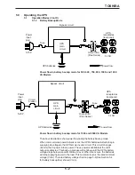
Power flow in AC input mode for 1500 and 2000 VA Models
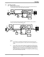
Both of the above illustrations show circuit power flow in the ac input mode.
The UPS unit's rectifier, included in a boost chopper circuit, converts ac input
power to dc power. This dc power runs the unit's transistor inverter and charges
the batteries. The boost chopper circuit maintains a constant voltage, with
current limiting, for charging the batteries and assures proper sine waveform
generation for the output current. The unit's batteries are maintained in a
constantly charged state when the UPS is in the normal operation mode.
_
Output Xfmr
(Plus Series)
Summary of Contents for 1400 Plus Series
Page 2: ...iii WARRENTY CARD INSERT ...
Page 3: ...iv WARRENTY CARD INSERT ...