background image

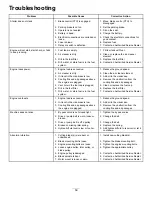
Troubleshooting

Problem

Possible Cause

Corrective Action

1. Blade control (PTO) is engaged.

1. Move blade contro (PTO) to

disengaged.

2. Parking brake is not on.

2. Set the parking brake.

3. Operator is not seated.

3. Sit on the seat.

4. Battery is dead.

4. Charge the battery.

5. Electrical connections are corroded or

loose.

5. Check the electrical connections for

good contact.

6. Fuse is blown.

6. Replace fuse.

Starter does not crank

7. Relay or switch is defective.

7. Contact an Authorized Service Dealer.

1. Fuel tank is empty.

1. Fill fuel tank with fuel.

2. Air cleaner is dirty.

2. Clean or replace the air cleaner

element.

3. Dirt in the fuel filter.

3. Replace the fuel filter.

Engine will not start, starts hard, or fails
to keep running.

4. Dirt, water, or stale fuel is in the fuel

system.

4. Contact an Authorized Service Dealer.

1. Engine load is excessive.

1. Reduce the ground speed.

2. Air cleaner is dirty.

2. Clean the air cleaner element.

3. Oil level in the crankcase is low.

3. Add oil to the crankcase.

4. Cooling fins and air passages above

the engine are plugged.

4. Remove the obstruction from the

cooling fins and air passages.

5. Vent hole in the fuel cap is plugged.

5. Clean or replace the fuel cap.

6. Dirt in the fuel filter.

6. Replace the fuel filter.

Engine loses power.

7. Dirt, water, or stale fuel is in the fuel

system.

7. Contact an Authorized Service Dealer.

1. Engine load is excessive.

1. Reduce the ground speed.

2. Oil level in the crankcase is low.

2. Add oil to the crankcase.

Engine overheats.

3. Cooling fins and air passages above

the engine are plugged.

3. Remove the obstruction from the

cooling fins and air passages.

1. By pass valve is not closed tight.

1. Tighten the by pass valve.

2. Drive or pump belt is worn, loose or

broken.

2. Change the belt.

3. Drive or pump belt is off a pulley.

3. Change the belt.

4. Broken or missing idler spring.

4. Replace the spring.

Machine does not drive.

5. Hydraulic fluid level is low or too hot.

5. Add hydraulic fluid to reservoir or let it

cool down.

1. Cutting blade(s) is/are bent or

unbalanced.

1. Install new cutting blade(s).

2. Blade mounting bolt is loose.

2. Tighten the blade mounting bolt.

3. Engine mounting bolts are loose.

3. Tighten the engine mounting bolts.

4. Loose engine pulley, idler pulley, or

blade pulley.

4. Tighten the appropriate pulley.

5. Engine pulley is damaged.

5. Contact an Authorized Service Dealer.

6. Blade spindle is bent.

6. Contact an Authorized Service Dealer.

Abnormal vibration.

7. Motor mount is loose or worn.

7. Contact an Authorized Service Dealer.

59

Summary of Contents for Z589 Z Master

Page 1: ...973 Rev C Z589 Z Master with a 60in or 72in TURBO FORCE Side Discharge Mower Model No 74253CP Serial No 270000101 and Up Model No 74254CP Serial No 270000101 and Up Register at www Toro com Original Instructions EN ...

Page 2: ...te and maintain your product properly and to avoid injury and product damage You are responsible for operating the product properly and safely You may contact Toro directly at www Toro com for product and accessory information help finding a dealer or to register your product Whenever you need service genuine Toro parts or additional information contact an Authorized Service Dealer or Toro Custome...

Page 3: ...uel Filters 36 Servicing the Fuel Tank 36 Electrical System Maintenance 37 Servicing the Battery 37 Servicing the Fuses 38 Drive System Maintenance 39 Adjusting the Tracking 39 Checking the Tire Pressure 40 Checking the Wheel Hub Slotted Nut 40 Adjusting the Caster Pivot Bearing 40 Servicing the Gear Box 41 Cooling System Maintenance 42 Servicing the Cooling System 42 Brake Maintenance 43 Adjustin...

Page 4: ...rea where the equipment is to be used and remove all objects such as rocks toys and wire which can be thrown by the machine Use extra care when handling gasoline and other fuels They are flammable and vapors are explosive Use only an approved container Never refuel or drain the machine indoors Never remove gas cap or add fuel with engine running Allow engine to cool before refueling Do not smoke C...

Page 5: ...e event of an emergency Be aware there is no rollover protection when the roll bar is down Check the area to be mowed and never fold the ROPS in areas where there are slopes drop offs or water Lower the rollbar only when absolutely necessary Do not wear the seat belt with the roll bar folded down Check carefully for overhead clearances i e branches doorways electrical wires before driving under an...

Page 6: ...Slope Chart 6 ...

Page 7: ...ructions are easily visible to the operator and are located near any area of potential danger Replace any decal that is damaged or lost 1 403005 1 523552 1 643253 54 9220 58 6520 1 Grease 66 1340 65 2690 68 8340 98 4387 1 Warning wear hearing protection 7 ...

Page 8: ...98 5954 105 7798 107 1613 107 1857 107 1860 107 1861 107 1864 8 ...

Page 9: ...107 2102 107 2112 107 2114 107 2449 108 5981 110 2067 9 ...

Page 10: ...fore servicing or performing maintenance 2 Continuous tone signals the user that engine is overheating 110 3853 1 Cutting dismemberment hazard fan and entanglement hazard belt 2 Remove the ignition key and read the instructions before servicing or performing maintenance 110 5772 1 Engine stop 5 Continuous variable setting 2 Engine run 6 Slow 3 Engine start 7 Power take off PTO 4 Fast 110 5794 110 ...

Page 11: ...110 6220 110 6221 Manufacturer s Mark 1 Indicates the blade is identified as a part from the original machine manufacturer 106 7492 11 ...

Page 12: ...106 9989 107 9309 1 Warning read the Operator s Manual for information on charging the battery contains lead do not discard 2 Read the Operator s Manual 110 0819 12 ...

Page 13: ...audible alarm that alerts the user to turn off the engine or engine damage can occur from over heating Refer to Servicing the Cooling System in Cooling System Maintenance page 42 Fuel Selector Valve The fuel selector valve is located under the left side of the seat Figure 5 Close the fuel selector valve when transporting or storing mower Move the selector valve to the lefthand LH or righthand RH p...

Page 14: ...n conditions during fueling static electricity can be released causing a spark which can ignite the gasoline vapors A fire or explosion from gasoline can burn you and others and can damage property Always place gasoline containers on the ground away from your vehicle before filling Do not fill gasoline containers inside a vehicle or on a truck or trailer bed because interior carpets or plastic tru...

Page 15: ... is located under the left side of the seat Unlatch the seat and raise it to access the valve The unit has two fuel tanks One tank is on the left side and one on the right side Each tank connects to the fuel selector valve From there a common fuel line leads to the engine Figure 5 To use the left side fuel tank rotate the fuel selector valve to the LH lefthand location To use the right side fuel t...

Page 16: ...re that the rear part of the seat is secured with the seat latch 4 To raise the roll bar remove the hairpin cotter pins and remove the two pins Figure 7 5 Raise the roll bar to the upright position and install the two pins and secure them with the hairpin cotter pins Figure 7 Important Always use the seat belt with the roll bar in the raised position G004955 1 2 3 4 Figure 7 1 Roll bar 3 Pin 2 Rai...

Page 17: ... sound levels in excess of 85 dBA at the operators ear and can cause hearing loss through extended periods of exposure Wear hearing protection when operating this machine The use of protective equipment for eyes ears feet and head is recommended Figure 9 1 Warning wear hearing protection Operating the Parking Brake Always set the parking brake when you stop the machine or leave it unattended Setti...

Page 18: ...e ignition key to the Start position Figure 13 When the engines starts release the key Important Do not engage starter for more than 5 seconds at a time If the engine fails to start allow a 15 second cool down period between attempts Failure to follow these instructions can burn out the starter motor Note Additional starting cycles may be required when starting the engine for the first time after ...

Page 19: ...could operate unexpectedly causing personal injury Do not tamper with the interlock switches Check the operation of the interlock switches daily and replace any damaged switches before operating the machine Understanding the Safety Interlock System The safety interlock system is designed to prevent the engine from starting unless You are sitting on the seat The parking brake is engaged The power t...

Page 20: ... the center un locked position 3 To go forward slowly push the motion control levers forward Figure 15 Note The engine will kill if the traction control levers are moved with the parking brake engaged To go straight apply equal pressure to both motion control levers Figure 15 To turn move the motion control lever toward neutral in the direction you want to turn Figure 15 The farther you move the t...

Page 21: ... cut lever 2 Clevis Pin Adjusting the Anti Scalp Rollers Whenever you change the height of cut it is recommended to adjust the height of the anti scalp rollers 1 Disengage the PTO move the motion control levers to the neutral locked position and set the parking brake 2 Stop the engine remove the key and wait for all moving parts to stop before leaving the operating position 3 After adjusting the h...

Page 22: ...hten the baffle and cam locks Figure 20 6 If the cams do not lock the baffle into place or it is too tight loosen the lever and then rotate the cam lock Adjust the cam lock until the desired locking pressure is achieved Figure 20 1 Cam lock 3 Rotate cam to increase or decrease locking pressure 2 Lever 4 Slot Positioning the Flow Baffle The following figures are only recommendations for use Adjustm...

Page 23: ... adjust move the lever sideways to unlock seat Figure 24 Figure 24 1 Seat suspension knob 2 Seat position adjustment lever 2 Slide the seat to the desired position and release lever to lock in position Changing the Seat Suspension The seat can be adjusted to provide a smooth and comfortable ride Position the seat where you are most comfortable To adjust it turn the knob in front either direction t...

Page 24: ...e the key 2 Rotate the by pass valves counterclockwise 1 turn to push This allows hydraulic fluid to by pass the pump enabling the wheels to turn Figure 27 Important Do not rotate by pass valves more than 1 turn This prevents valves from coming out of the body and causing fluid to run out 3 Disengage parking brake before pushing Changing to Machine Operation Rotate the by pass valves clockwise 1 t...

Page 25: ...ropes Secure a trailer to the towing vehicle with safety chains Driving on the street or roadway without turn signals lights reflective markings or a slow moving vehicle emblem is dangerous and can lead to accidents causing personal injury Do not drive machine on a public street or roadway Loading Machines Use extreme caution when loading units on trailers or trucks One full width ramp that is wid...

Page 26: ...he Z Stand The Z Stand raises the front end of the machine to allow you to clean the mower and remove the blades The machine could fall onto someone and cause serious injury or death Use extreme caution when operating the machine on the Z Stand Use only for cleaning the mower and removing the blades Do not keep the machine on the Z Stand for extended periods of time Always turn the engine off set ...

Page 27: ... slightly longer than normal to ensure the cutting height of the mower does not scalp any uneven ground However the cutting height used in the past is generally the best one to use When cutting grass longer than six inches tall you may want to cut the lawn twice to ensure an acceptable quality of cut Cut 1 3 of the Grass Blade It is best to cut only about 1 3 of the grass blade Cutting more than t...

Page 28: ...he mower cutting quality will eventually become unsatisfactory Blade Maintenance Maintain a sharp blade throughout the cutting season because a sharp blade cuts cleanly without tearing or shredding the grass blades Tearing and shredding turns grass brown at the edges which slows growth and increases the chance of disease Check the cutter blades daily for sharpness and for any wear or damage File d...

Page 29: ...e belt Every 100 hours Change the engine oil more often in dirty or dusty conditions Check the spark plug Check the gear box oil level Check the cooling system hoses Inspect the belts for cracks and wear Check the hydraulic hoses Every 150 hours Lubricate the machine with light oil Every 200 hours Change the engine oil filter Grease the brake pivot Every 250 hours Check or replace the air filter m...

Page 30: ... Wipe up any excess grease Greasing the Front Caster Pivots Service Interval Yearly more often in dirty or dusty conditions 1 Remove the dust cap and adjust the caster pivots Keep the dust cap off until greasing is done Refer to Adjusting the Caster Pivot Bearing in Drive System Maintenance page 39 2 Remove the hex plug Thread a grease zerk into the hole 3 Pump grease into the zerk until it oozes ...

Page 31: ...engine remove the key and wait for all moving parts to stop before leaving the operating position 3 Grease the idler pulley pivot Figure 33 4 Grease the fittings on the 3 spindle bearings Figure 33 Figure 33 5 Grease the pump belt idler arm Figure 34 Figure 34 6 Grease the PTO drive belt idler arm Figure 35 Figure 35 31 ...

Page 32: ... cover with compressed air 7 Gently slide the filter out of the air cleaner body Figure 36 Avoid knocking the filter into the side of the body 8 Inspect the filter for damage by looking into the filter while shining a bright light on the outside of the filter Holes in the filter will appear as bright spots If the filter is damaged discard it Figure 36 1 Air cleaner cover 3 Air filter body 2 Air fi...

Page 33: ...ully into the engine Pull the dipstick out and look at the metal end Figure 38 If oil level is low slowly pour only enough oil into the filler tube to raise the level to the full mark Important Do not overfill the crankcase with oil because the engine may be damaged Do not run engine with oil below the low mark because the engine may be damaged Changing the Oil Service Interval After the first 8 h...

Page 34: ...Figure 41 Figure 41 1 Engine oil filter 3 Apply a thin coat of new oil to the rubber gasket on the replacement filter Figure 42 4 Install the replacement oil filter to the filter adapter Turn the oil filter clockwise until the rubber gasket contacts the filter adapter then tighten the filter an additional 1 2 turn Figure 42 Figure 42 1 Oil filter 3 Adapter 2 Gasket 5 Fill the crankcase with the pr...

Page 35: ...rs 1 Look at the center of the spark plug s Figure 44 If you see light brown or gray on the insulator the engine is operating properly A black coating on the insulator usually means the air cleaner is dirty Important Never clean the spark plug s Always replace the spark plug s when it has a black coating worn electrodes an oily film or cracks Figure 44 1 Canter electrode insulator 3 Air gap not to...

Page 36: ...ng by an Authorized Service Dealer is necessary Servicing the Fuel Filters Replacing the Fuel Filter Service Interval Every 400 hours or yearly which ever comes first more often in dirty or dusty conditions Ensure that an Authorized Service Dealer replaces the fuel filter and any components for the fuel system Use of improper components can result in system failure fuel leakage and possible explos...

Page 37: ...achine Incorrect battery cable routing could damage the machine and cables causing sparks Sparks can cause the battery gasses to explode resulting in personal injury Always Disconnect the negative black battery cable before disconnecting the positive red cable Always Reconnect the positive red battery cable before reconnecting the negative black cable 1 Disengage the PTO move the motion control le...

Page 38: ...nt to prevent battery damage when the temperature is below 32 F 0 C 1 Make sure the filler caps are installed in battery Charge battery for 10 to 15 minutes at 25 to 30 amps or 30 minutes at 10 amps 2 When the battery is fully charged unplug the charger from the electrical outlet then disconnect the charger leads from the battery posts Figure 48 3 Install the battery in the machine and connect the...

Page 39: ...c Pump Neutral in Hydraulic System Maintenance page 48 1 Push both control levers forward the same distance 2 Check if the machine pulls to one side If it does stop the machine and set the parking brake 3 Unlatch the seat and tilt the seat forward to access the tracking knob Note Determine the left and right sides of the machine from the normal operating position 4 To make the machine go right tur...

Page 40: ...gine remove the key and wait for all moving parts to stop before leaving the operating position 3 Remove the cotter pin 4 Check the distance from bottom of slot in nut to inside edge of hole Two threads or less should be showing Figure 52 Figure 52 1 Slotted Nut 3 Hole in threaded shaft 2 Two threads or less showing 4 Washer if needed 5 If more than two threads are showing remove nut and install w...

Page 41: ...neutral locked position and set the parking brake 3 Stop the engine remove the key and wait for all moving parts to stop before leaving the operating position 4 Loosen the lug nuts on the right rear wheel 5 Raise rear of the machine so the right rear wheel is off the ground and support the machine with jack stands 6 Remove the right rear wheel from the machine 7 Locate the hole in the frame and re...

Page 42: ...irst 8 hours Every 100 hours Fluid Type 50 50 mix of extended life antifreeze Dex Cool and water Cooling System Capacity 156 ounces 4 6 l Note Do not open the radiator cap Doing this may induce air into the cooling system 1 Position the machine on a level surface stop the engine and set the parking brake 2 Unlatch the seat and tilt the seat up 3 With the engine cool check the overflow bottle level...

Page 43: ...justment is necessary release the parking brake loosen the jam nut below the spring and adjust the nut directly below the spring Figure 57 Turn the nut until the correct measurement is obtained Turn the nut clockwise to shorten spring length and turn counter clockwise to lengthen the spring 4 Tighten the two nuts together 5 Engage the parking brake lever up Check the measurement of the spring agai...

Page 44: ...ulley under the engine Figure 59 7 Install spring to the idler arm Figure 59 8 Install the belt guide on the spring loaded idler at a 45 degree angle as shown in Figure 59 9 Install the belt covers by sliding the cover into the tab install the bolts and close the latches Figure 58 Figure 58 1 Belt cover 3 Insert slot into the tab 2 Latch Figure 59 1 Mower belt 4 Belt guide 2 Mower spindle pulley 5...

Page 45: ...e belt covers by sliding the cover into the tab install the bolts and close the latches Figure 62 Figure 62 1 Belt cover 3 Insert slot into the tab 2 Latch Adjusting the Mower Belt Tension for 72 inch Mower Decks Service Interval After the first 8 hours Important To ensure proper mower belt tension which will result in a longer belt life check the mower belt tension after the first 8 hours of use ...

Page 46: ...the PTO move the motion control levers to the neutral locked position and set the parking brake 2 Stop the engine remove the key and wait for all moving parts to stop before leaving the operating position 3 Loosen the front engine panel knobs and remove the panel Figure 64 Figure 64 1 Knob 2 Front engine panel 4 Remove the spring from the idler arm Figure 65 5 Remove the clutch stop bracket 6 Remo...

Page 47: ... See Installing the Motion Control Levers in the set up instructions 1 Disengage the PTO move the motion control levers to the neutral locked position and set the parking brake 2 Stop the engine remove the key and wait for all moving parts to stop before leaving the operating position 3 Unlatch the seat and tilt the seat forward 4 Begin with either the left or right motion control lever 5 Move the...

Page 48: ...nterval After the first 8 hours Check the hydraulic fluid Every 25 hours Check the hydraulic fluid Note There are two ways of checking the hydraulic oil One is when the oil is warm and one is when the oil is cold The baffle inside the tank has two levels depending if the oil is warm or cold 1 Position the machine on a level surface and set the parking brake 2 Clean the area around filler neck of h...

Page 49: ...tral locked position and set the parking brake 2 Stop the engine remove the key and wait for all moving parts to stop before leaving the operating position Important Do not substitute automotive oil filter or severe hydraulic system damage may result 3 Place drain pan under filter remove the old filter and wipe the filter adapter gasket surface clean Figure 70 Figure 70 1 Hydraulic filter 4 Remove...

Page 50: ...ake necessary repairs before operating Note Keep areas around the hydraulic system clean from grass and debris build up Hydraulic fluid escaping under pressure can penetrate skin and cause injury If hydraulic fluid is injected into the skin it must be surgically removed within a few hours by a doctor familiar with this type of injury Gangrene may result if this is not done Keep body and hands away...

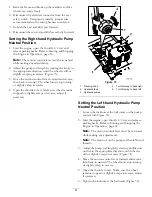
Page 51: ...Open the throttle to fast Make sure wheel remains stopped or slightly creeps in reverse adjust if necessary Figure 73 1 Tracking knob 4 Turn this way to track right 2 Hydraulic tank 5 Turn this way to track left 3 Hydraulic pumps Setting the Left hand Hydraulic Pump Neutral Position 1 Loosen the locknuts at the ball joints on the pump control rod Figure 74 2 Start the engine open throttle 1 2 way ...

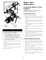
Page 52: ...arking brake 3 Stop the engine remove the key and wait for all moving parts to stop before leaving the operating position 4 Check tire pressure of all four tires If needed adjust to 13 psi 90 kPa 5 Lower the mower to the 3 inch 76 mm height of cut position 6 Inspect the four chains The chains need to have tension If one rear chain is loose lower loosen the front support arm on the same side Refer ...

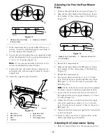
Page 53: ...edge of the blade tip Figure 77 Figure 77 1 Measure here from blade to hard surface 2 Measure at A and B 3 Record this measurement 4 Measure the right blade at the B location from a level surface to the cutting edge of the blade tip Figure 77 5 Record this measurement 6 The mower blade should be a 1 4 to 3 8 inch 6 to 10 mm lower at position A than at position B Figure 77 If it is not correct proc...

Page 54: ...e chance of disease Check the cutter blades daily for sharpness and for any wear or damage File down any nicks and sharpen the blades as necessary If a blade is damaged or worn replace it immediately with a genuine Toro replacement blade For convenient sharpening and replacement you may want to keep extra blades on hand A worn or damaged blade can break and a piece of the blade could be thrown int...

Page 55: ...utting edge of the blades at the same position as in step 3 above The difference between the dimensions obtained in steps 3 and 4 must not exceed 1 8 inch 3 mm If this dimension exceeds 1 8 inch 3 mm the blade is bent and must be replaced refer to Removing the Blades and Installing the Blades A blade that is bent or damaged could break apart and could seriously injure or kill you or bystanders Alw...

Page 56: ...shaft Figure 83 Important The curved part of the blade must be pointing upward toward the inside of the mower to ensure proper cutting 2 Install the spring disk and blade bolt The spring disk cone must be installed toward the bolt head Figure 83 Torque the blade bolt to 85 110 ft lb 115 150 N m Figure 83 1 Sail Area of Blade 4 Blade Bolt 2 Blade 5 Cone Towards Bolt Head 3 Spring Disk Replacing the...

Page 57: ...nder the Mower Service Interval Before each use or daily 1 Disengage the PTO move the motion control levers to the neutral locked position and set the parking brake 2 Stop the engine remove the key and wait for all moving parts to stop before leaving the operating position 3 Raise the mower to the transport position 4 Remove the grass buildup under the mower deck Waste Disposal Engine oil batterie...

Page 58: ...ide of the mower then wash the mower with a garden hose Note Run the machine with the PTO engaged and the engine at high idle for 2 to 5 minutes after washing 11 Check the condition of the blades refer to Servicing the Cutting Blades in Mower Deck Maintenance page 52 12 Prepare the machine for storage when non use occurs over 30 days Prepare the machine for storage as follows A Add a petroleum bas...

Page 59: ...ugged 5 Clean or replace the fuel cap 6 Dirt in the fuel filter 6 Replace the fuel filter Engine loses power 7 Dirt water or stale fuel is in the fuel system 7 Contact an Authorized Service Dealer 1 Engine load is excessive 1 Reduce the ground speed 2 Oil level in the crankcase is low 2 Add oil to the crankcase Engine overheats 3 Cooling fins and air passages above the engine are plugged 3 Remove ...

Page 60: ...tall deck pulley and check the idler pulley idler arm and spring for correct position and function Blades do not rotate 5 Broken or missing idler spring 5 Replace the spring 1 Engine is too hot 1 Turn engine off and let it cool 2 Old gas in the gas tank 2 Use new gas 3 The fuel shut off valve is not open completely 3 Open the fuel shut off valve 4 Fuel tank vent cap is blocked 4 Make sure that the...

Page 61: ...Schematics Wire Diagram Rev A 61 ...

Page 62: ...Notes 62 ...

Page 63: ... A Italy 39 0331 853611 Irriamc Portugal 351 21 238 8260 Jean Heybroek b v Netherlands 31 30 639 4611 Lely U K Limited United Kingdom 44 1480 226 800 Maquiver S A Columbia 57 1 236 4079 Maruyama Mfg Co Inc Japan 81 3 3252 2285 Metra Kft Hungary 36 1 326 3880 Mount eld a s Czech Republic 420 255 704 220 Munditol S A Argentina 54 11 4 821 9999 Oslinger Turf Equipment SA Ecuador 593 4 239 6970 Oy Hak...

Page 64: ...f the product If for any reason it is impossible for you to contact your seller you may contact any Toro Authorized Distributor to arrange service 2 Bring the product and your proof of purchase sales receipt to your seller or the Service Dealer If for any reason you are dissatis ed with the Service Dealer s analysis or with the assistance provided contact the Toro importer or contact us at Custome...

Reviews: