Drive System
Maintenance
Checking the Tire Pressure
Check the pressure at the valve stem after every
50 operating hours or monthly, whichever occurs
first (Figure 41).
Maintain the air pressure in the rear tires at 13 psi
(90 kPa). Uneven tire pressure can cause uneven
cut. Check the tires when they are cold to get the
most accurate pressure reading.
Note:
The front tires are semi-pneumatic tires
and do not require air pressure maintenance.
Figure 41
Adjusting the Caster Pivot
Bearing
Check after every 500 operating hours or at
storage, which ever comes first.
1. Disengage the PTO, move the motion control
levers to the neutral locked position and set
the parking brake.
2. Stop the engine, remove the key, and wait for
all moving parts to stop before leaving the
operating position.
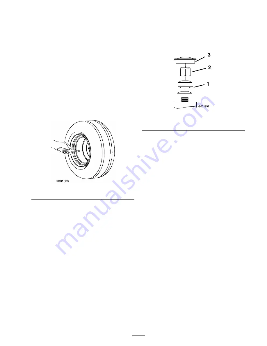
3. Remove the dust cap from caster and tighten
lock nut (Figure 42).
4. Tighten the locknut until the spring washers
are flat and then back off a 1/4 turn to properly
set the pre-load on the bearings (Figure 42).
Important:
Make sure spring washers
are installed correctly as shown in
Figure 42.
5. Install the dust cap (Figure 42).
Figure 42
1. Spring Washers
3. Dust Cap
2. Lock Nut
Cooling System
Maintenance
Cleaning the Air Intake
Screen
Before each use remove any build-up of grass, dirt
or other debris from the cylinder and cylinder head
cooling fins, air intake screen on flywheel end, and
carburetor-governor levers and linkage. This will
help insure adequate cooling and correct engine
speed and will reduce the possibility of overheating
and mechanical damage to the engine.
Cleaning the Cooling System
Clean the air intake screen from grass and debris
before each use.
Check and clean cooling fins and engine shrouds
every 100 hours or yearly, which ever comes first.
1. Disengage the PTO and set the parking brake.
2. Stop the engine, remove the key, and wait for
all moving parts to stop before leaving the
operating position.
3. Remove the guard, air intake screen and fan
housing (Figure 43).
37
Summary of Contents for Z334 Z-Master
Page 8: ...Slope Chart 8 ...
Page 44: ...Figure 53 1 Keep the end of the bolt ush with the nut 3 Nut 2 Rear pivot bracket 4 Bolt 44 ...
Page 54: ......
Page 55: ......


