


g018440
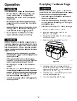
Figure 31
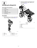
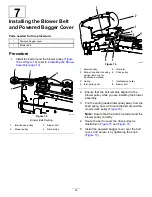
1.
Upper tube
3.
Bagger hood
2.
Rubber seal protruding out
10.
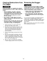
Align the upper tube holes to match the dimples
on the surface of the lower tube.
Note:
Ensure that the side profile appears as
shown in
.
Note:
Do not use the open hole near the
molded arrowheads.
g020776
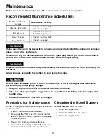
Figure 32
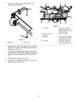
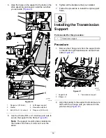
1.
Upper tube
3.
Notch at the bottom of the
tube when installed
2.
Existing hole (bolt
removed)
4.
Lower tube
11.
Using the existing holes in the upper tube as
a template, drill 2 holes, 6.5 mm (1/4 inch)
diameter, through the dimples on the lower tube
(
).
g018439
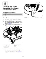
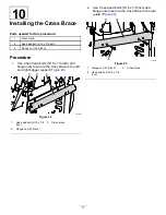
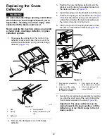
Figure 33
Drilling Lower Discharge Tube
1.
Dimples
4.
Upper tube
2.
Lower tube
5.
Install screw (1/4 x 3/4
inch), washer (1/4 inch),
and locknut (1/4 inch)
here.
3.
Drill 6.5 mm (1/4 inch)
diameter hole
6.
Upper tube—existing
holes
12.
Remove the upper and lower tubes from the
machine.
13.
Slide the tubes together and align the holes.
14.
Install the washers (1/4 inch) onto the bolts
(
).
15.
Using a hex key tool, install the screws (1/4 x
3/4 inch) and washers (1/4 inch) from the inside
of the lower tube and through the existing holes
in the upper tube (
).
22


