background image

Safety and Instructional Decals

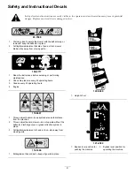
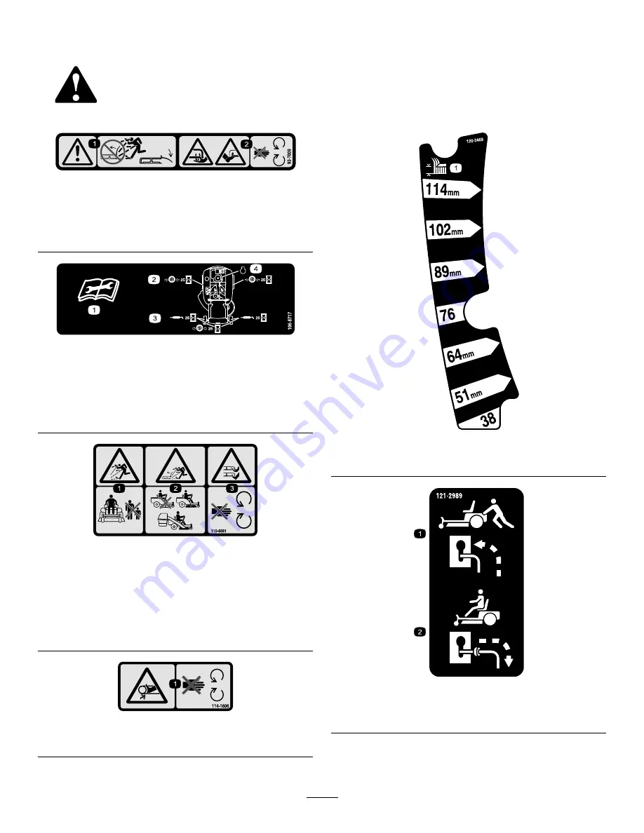
Safety decals and instructions are easily visible to the operator and are located near any area of potential
danger. Replace any decal that is damaged or lost.

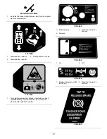
93-7009

1.

Warning—don't operate the mower with the deflector up or
removed; keep the deflector in place.

2.

Cutting/dismemberment hazard of hand or foot, mower
blade—stay away from moving parts.

106-8717

1.

Read the instructions before servicing or performing
maintenance.

2.

Check tire pressure every 25 operating hours.

3.

Grease every 25 operating hours.

4.

Engine

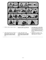
110-6691

1.

Thrown object hazard—keep bystanders a safe distance
from the machine.

2.

Thrown object hazard, mower—do not operate without the
deflector, discharge cover, or grass collection system in
place.

3.

Cutting/dismemberment of hand or foot—stay away from
moving parts.

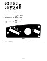
114-1606

1.

Entanglement hazard, belt—keep all guards in place.

120-5469

1.

Height-of-cut

121-2989

1.

Bypass lever position for
pushing the machine

2.

Bypass lever position for
operating the machine

9


Summary of Contents for TimeCutter SW3200

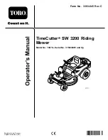
Page 1: ...Form No 3393 645 Rev C TimeCutter SW 3200 Riding Mower Model No 74670 Serial No 315000001 and Up g027913 Register at www Toro com Original Instructions EN 3393 645 C ...

Page 2: ... and maintain your product properly and to avoid injury and product damage You are responsible for operating the product properly and safely You may contact Toro directly at www Toro com for product safety and operation training materials accessory information help finding a dealer or to register your product Whenever you need service genuine Toro parts or additional information contact an Authori...

Page 3: ...chedule s 27 Premaintenance Procedures 27 Raising the Seat 27 Releasing the Mower Deck Curtain 28 Raising the Front of the Machine 28 Lubrication 28 Greasing the Bearings 28 Engine Maintenance 29 Servicing the Air Cleaner 29 Servicing the Engine Oil 30 Servicing the Spark Plug 33 Cleaning the Blower Housing 34 Fuel System Maintenance 34 Replacing the In line Fuel Filter 34 Electrical System Mainte...

Page 4: ...ropriate clothing including a hard hat substantial slip resistant footwear long pants gloves and hearing protection Important Long hair loose clothing or jewelry may get tangled in moving parts Inspect the area where the equipment is to be used and ensure that all objects are removed from the machine before use Use extra care when handling fuels They are flammable and vapors are explosive Use only...

Page 5: ...ment from the truck or trailer and fuel it on the ground If this is not possible then add fuel with such equipment as a portable container rather than from a fuel dispenser nozzle Keep the nozzle in contact with the rim of the fuel tank or container opening at all times until fueling is complete Do not use a nozzle lock open device If fuel is spilled on clothing change your clothing immediately Do...

Page 6: ...area Watch for holes ruts or bumps Note Tall grass can hide obstacles Use caution near drop offs ditches or embankments Note The machine could suddenly turn over if a wheel goes over the edge of a cliff or ditch or if an edge caves in Use extra care with grass catchers or other attachments Note These can change the stability of the machine Keep all movement on slopes slow and gradual Do not make s...

Page 7: ... guaranteed sound power level of 100 dBA which includes an Uncertainty Value K of 1 dBA Sound pressure level was determined according to the procedures outlined in EN ISO 5395 2013 Hand Arm Vibration Measured vibration level for left hand 1 7 m s2 Measured vibration level for right hand 1 8 m s2 Uncertainty Value K 0 9 m s2 Measured values were determined according to the procedures outlined in EN...

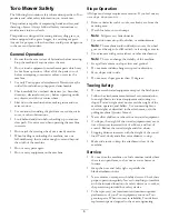
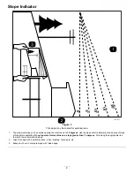
Page 8: ... degrees Use the slope chart to determine the degree of slope of hills before operating Do not operate this machine on a slope greater than 15 degrees Fold along the appropriate line to match the recommended slope 2 Align this edge with a vertical surface a tree building fence pole etc 3 Example of how to compare slope with folded edge 8 ...

Page 9: ...tructions before servicing or performing maintenance 2 Check tire pressure every 25 operating hours 3 Grease every 25 operating hours 4 Engine 110 6691 1 Thrown object hazard keep bystanders a safe distance from the machine 2 Thrown object hazard mower do not operate without the deflector discharge cover or grass collection system in place 3 Cutting dismemberment of hand or foot stay away from mov...

Page 10: ...sition reverse 2 Pedal position neutral 131 3621 1 Crushing dismemberment hazard of bystanders keep bystanders away from the machine do not start the machine with bystanders nearby 131 3665 1 Blade spinning 3 Read the Operator s Manual 2 Reverse 131 3955 1 On 2 Off 131 4036 1 Maximum drawbar pull 80 lbs 36 kg 2 Read the Operator s Manual 132 6863 10 ...

Page 11: ...e less than 15 degrees back up the ramp in reverse and drive forward off the ramp 2 Cutting hazard of hand mower blade pinching hazard of hand belt keep hands and feet away from moving parts keep all guards and shields in place 4 Thrown object hazard keep bystanders away from the machine remove debris from the area before mowing keep the deflector shield down 6 Tipping hazard on slopes do not make...

Page 12: ...plosive gases can cause blindness and other injuries 3 Caustic liquid chemical burn hazard 8 Battery acid can cause blindness or severe burns 4 Wear eye protection 9 Flush eyes immediately with water and get medical help fast 5 Read the Operator s Manual 10 Contains lead do not discard 121 0771 1 Choke 4 Slow 2 Fast 5 Power take off PTO Blade control switch 3 Continuous variable setting 12 ...

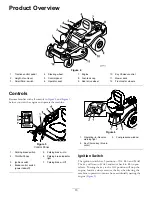
Page 13: ...027892 Figure 5 Control Panel 1 Parking brake switch 5 Parking brake On 2 Throttle Choke 6 Parking brake indicator light 3 Ignition switch 7 Parking brake Off 4 Blade control switch power take off Figure 6 1 Operating in Reverse warning light 3 Fuel presence window 2 Key Choice key blue in color Ignition Switch The ignition switch has 3 positions OFF RUN and START The key will turn to START and mo...

Page 14: ...in reverse when it is activated To activate it turn the switch to on and release it after the PTO is engaged To deactivate it disengage the power take off PTO Figure 6 Operating in Reverse Warning Light The Operating in Reverse warning light will illuminate whenever the KeyChoice key is used to deactivate the operating in reverse interlock It is a reminder that the interlock system is deactivated ...

Page 15: ...pace in the tank allows gasoline to expand Never smoke when handling gasoline and stay away from an open flame or where gasoline fumes may be ignited by a spark Store gasoline in an approved container and keep it out of the reach of children Never buy more than a 30 day supply of gasoline Do not operate without entire exhaust system in place and in proper working condition DANGER In certain condit...

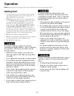
Page 16: ...Ensure that the engine is shut off and the motion controls are in the parked position Note You can use the fuel window to verify the presence of gasoline before filling the tank Figure 7 Important Do not overfill fuel tank Fill the fuel tank to the bottom of the filler neck The empty space in the tank allows the fuel to expand Overfilling may result in fuel leakage damage to the engine or damage t...

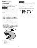
Page 17: ... When mowing slopes gradually work from lower to higher areas on the incline Avoid sudden turns or rapid speed changes Turn up into an incline when changing directions on slopes Turning down the slope reduces traction Attachments change the handling characteristics of the machine Use extra caution when using attachments with the machine g027830 Figure 8 1 Safe zone use the TimeCutter here 3 Water ...

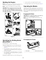
Page 18: ...switch to the START position Note The PTO should disengage and the engine should crank 7 Ensure the traction control pedal is in the neutral position and start the engine 8 Raise from the seat Note The engine should remain running 9 Return to the seat disengage the parking brake by pushing the SmartPark switch to the OFF position Note The engine should remain running 10 Raise from the seat Note Th...

Page 19: ...es the seat and the traction control pedal is in the neutral position The parking brake automatically engages 5 to 6 seconds after the ignition switch is turned to the OFF position if not already engaged Disengage the parking brake by one of the following actions Tap the traction control pedal forward or reverse Pressing the brake switch to the OFF position Figure 5 Operating the Blades The blade ...

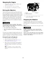
Page 20: ...tes the engine speed as measured in rpm revolutions per minute Placing the throttle control in the FAST position can be best for performance For most applications operating in the full throttle position is desirable Driving Forward or Backward 1 Move the throttle to the FAST position 2 Release the parking brake Refer to Operating the Parking Brake SmartPark page 19 3 Place your foot onto the tract...

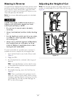
Page 21: ... and put them in a safe place out of the reach of children or unauthorized users when leaving the unit unattended If you are certain that you can safely mow or operate an attachment in reverse complete the following procedure 1 Insert the KeyChoice key into the KeyChoice switch Figure 6 2 Engage the PTO 3 Turn the KeyChoice key clockwise until it stops and release it Note A red light illuminates o...

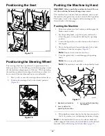
Page 22: ...tric brake to be disengage Pushing the Machine 1 Park the machine on a level surface and disengage the blade control switch 2 Set the parking brake stop the engine and wait for all moving parts to stop before leaving the operating position 3 Locate the bypass levers on the frame on both sides of the engine 4 Move the bypass levers forward through the key hole and down to lock them in place Figure ...

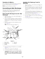
Page 23: ...ge pin 2 Discharge cover 5 Wing nut 3 Lower lip 4 Remove the hinge pin securing the cover to the deck Figure 18 5 Lift the cover out and away from the deck 6 Lower the grass deflector over the discharge opening Important Ensure that the mower has a hinged grass deflector that disperses clippings to the side and down toward the turf while in side discharge mode Installing the Discharge Cover for Mu...

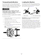
Page 24: ...els and the rear bumper Figure 19 Note Avoid the steering components when tying down the machine at the front caster wheels Figure 19 Loading the Machine Use extreme caution when loading or unloading machines onto a trailer or a truck Use a full width ramp that is wider than the machine for this procedure Back up ramps and drive forward down ramps Figure 20 Figure 20 1 Back up ramps 2 Drive forwar...

Page 25: ... as long as the height of the trailer or truck bed to the ground This will ensure that ramp angle does not exceed 15 degrees on flat ground Back up ramps and drive forward down ramps Avoid sudden acceleration or deceleration while driving the machine on a ramp as this could cause a loss of control or a tip over situation g027996 5 1 2 6 Figure 21 1 Full width ramp in stowed position 4 Ramp is at l...

Page 26: ...d summer mow less frequently If you cannot mow for an extended period first mow at a high cutting height then mow again 2 days later at a lower height setting Avoiding Cutting Too Low If the cutting width of the mower is wider than the mower you previously used raise the cutting height to ensure that uneven turf is not cut too short Cutting Long Grass If the grass is ever allowed to grow slightly ...

Page 27: ...il change it more often under a heavy load or in high temperatures Change the engine oil filter Replace the spark plug Clean the blower housing more often under extremely dusty dirty conditions Replace the in line fuel filter Before storage Charge the battery and disconnect battery cables Perform all maintenance procedures listed above before storage Paint any chipped surfaces CAUTION If you leave...

Page 28: ...eral purpose lithium base grease 1 Park the machine on a level surface and disengage the blade control switch 2 Set the parking brake stop the engine remove the key and wait for all moving parts to stop before leaving the operating position 3 Clean the grease fittings Figure 24 and Figure 25 with a rag Note Make sure to scrape any paint off of the front of the fitting s Figure 24 1 Front caster ti...

Page 29: ... Element 1 Wash the foam element in liquid soap and warm water 2 When the element is clean rinse it thoroughly 3 Dry the element by squeezing it in a clean cloth Note Do not oil the element Important Replace the foam element if it is torn or worn 4 Install the foam element onto a clean paper element Paper Element 1 Tap the paper element on a solid flat surface and blow it out from the inside with ...

Page 30: ...ly Note Check the oil when the engine is cold WARNING Contact with hot surfaces may cause personal injury Keep hands feet face clothing and other body parts away the muffler and other hot surfaces Important Do not overfill the crankcase with oil and run the engine engine damage may result 1 Park the machine on a level surface 2 Disengage the blade control switch PTO 3 Stop the engine wait for all ...

Page 31: ...e frequently when the operating conditions are extremely dusty or sandy 1 Park the machine so that the right side is slightly lower than the left side to ensure that the oil drains completely 2 Disengage the blade control switch PTO 3 Stop the engine wait for all moving parts to stop and remove the key before leaving the operating position 4 Drain the oil from the engine B A C E F D G H g029369 Fi...

Page 32: ... gasket touches the engine and then turn the filter an extra 3 4 turn B A C D E F 3 4 g027477 Figure 31 6 Slowly pour approximately 80 of the specified amount of oil into the fill hole Figure 32 7 Check the oil level refer to Figure 32 B A C D E F g027484 Figure 32 32 ...

Page 33: ... the motion controls outward to the PARK position stop the engine and remove the key 2 Before removing the spark plug s clean the area around the base of the plug to keep dirt and debris out of the engine 3 Remove the spark plug Figure 33 B A g027478 Figure 33 Checking the Spark Plug Important Do not clean the spark plug s Always replace the spark plug s when it has a black coating worn electrodes...

Page 34: ...rque the blower housing screws to 7 5 N m 5 5 ft lb Important Operating the engine with a blocked grass screen dirty or plugged cooling fins and or cooling shrouds removed will cause engine damage due to overheating Fuel System Maintenance Replacing the In line Fuel Filter Service Interval Every 100 hours Replace the in line fuel filter Never install a dirty filter if it is removed from the fuel l...

Page 35: ...ine on a level surface and disengage the blade control switch 2 Set the parking brake stop the engine remove the key and wait for all moving parts to stop before leaving the operating position 3 Raise the seat to access the battery 4 Disconnect the negative black ground cable from the battery post Figure 37 Note Retain all fasteners WARNING Incorrect battery cable routing could damage the machine ...

Page 36: ... fasteners previously removed install the negative battery cable to the negative battery terminal 4 Slide the red terminal boot onto the positive red battery post 5 Secure the battery with the hold down Figure 37 6 Lower the seat Servicing the Fuses The electrical system is protected by fuses It requires no maintenance however if a fuse blows check the component circuit for a malfunction or short ...

Page 37: ...dewall of the caster wheel tires Inflate the rear drive wheel tires to 89 6 kPa 13 psi Figure 40 1 Valve stem Releasing the Electric Brake The electric brake releases by manually rotating the link arms forward Once the electric brake is energized the brake will reset To release the brake 1 Turn the ignition key to the OFF position or disconnect the battery 2 Locate the shafts where the brake link ...

Page 38: ... machine on a level surface disengage the blade control switch stop the engine and remove the key Inspecting the Blades Service Interval Before each use or daily Check the cutting blades 1 Inspect the cutting edges Figure 42 Note If the edges are not sharp or have nicks remove and sharpen the blades refer to Sharpening the Blades page 40 2 Inspect the blades especially the curved area Figure 42 No...

Page 39: ... blade to the flat surface Figure 46 Note The variance should be no more than 3 mm 1 8 inch G009680 1 2 3 Figure 46 1 Opposite blade edge in position for measuring 2 Level surface 3 Second measured distance between blade and surface B A If the difference between A and B is greater than 3mm 1 8 inch replace the blade with a new blade refer to Removing the Blades page 40 and Installing the Blades pa...

Page 40: ...lade Figure 48 Note Maintain the original angle Note The blade retains its balance if the same amount of material is removed from both cutting edges Figure 48 1 Sharpen at original angle 2 Check the balance of the blade by putting it on a blade balancer Figure 49 Note If the blade stays in a horizontal position the blade is balanced and can be used Note If the blade is not balanced file some metal...

Page 41: ...ever to middle position 4 Carefully rotate the blade s so that they are all side to side Figure 50 G014630 1 2 3 4 4 Figure 50 1 Blade side to side 3 Outside cutting edges 2 Sail area of the blade 4 Measure from the tip of the blade to the flat surface here 5 Measure between the outside cutting edges and the flat surface Figure 50 If both measurements are not within 5 mm 3 16 inch an adjustment is...

Page 42: ... 1 blade 1 Blade front to rear 2 Measure from the tip of the blade to the flat surface here 5 Measure from the tip of the front blade to the flat surface and the tip of the rear blade to the flat surface Figure 52 Note If the front blade tip is not 1 6 to 7 9 mm 1 16 to 5 16 inch lower than the rear blade tip adjust the front locknut 6 To adjust the front to rear blade slope rotate the adjustment ...

Page 43: ...the rod from the deck bracket Figure 54 Carefully lower the front of the mower deck to the ground G014635 1 2 3 Figure 54 1 Front support rod 3 Deck bracket 2 Locking nut 5 Lift the mower deck and hanger brackets clear of the rear lift rod and lower the mower carefully to the ground Figure 55 G015338 2 2 3 1 2 2 3 Figure 55 1 Mower deck 3 Rear lift rod 2 Hanger bracket 6 Slide the mower deck rearw...

Page 44: ...e spring is under tension when installed and can cause personal injury Be careful when removing the belt G015129 1 2 3 4 5 4 6 Figure 56 Mower decks with 1 blade 1 Idler pulley 4 Spring 2 Mower belt 5 Engine pulley 3 Outside pulley 6 Spring removal tool 5 Route the new belt around the engine pulley and mower pulleys Figure 56 6 Using a spring removal tool Toro part no 92 5771 install the idler spr...

Page 45: ...Grass deflector 6 Nut 3 8 inch 3 Grass deflector bracket 7 Short standoff 4 Rod 2 Remove the nut 3 8 inch from the rod under the mower Figure 57 3 Slide the rod out of the short stand off spring and grass deflector Figure 57 4 Remove the damaged or worn grass deflector 5 Replace the grass deflector Figure 57 6 Slide the rod straight end through the rear grass deflector bracket 7 Place the spring o...

Page 46: ... leaving the operating position 3 Attach the hose coupling to the end of the mower washout fitting and turn the water on high Figure 59 Note Spread petroleum jelly on the washout fitting O ring to make the coupling slide on easier and protect the O ring Figure 59 1 Washout fitting 3 O ring 2 Hose 4 Coupling 4 Lower the mower to the lowest height of cut 5 Sit on the seat and start the engine 6 Enga...

Page 47: ...hol based stabilizer ethanol or methanol Note A fuel stabilizer conditioner is most effective when mixed with fresh gasoline and used at all times Run the engine to distribute the conditioned fuel through the fuel system 5 minutes Stop the engine allow it to cool and drain the fuel tank Restart the engine and run it until it stops Choke the engine Start and run the engine until it will not start D...

Page 48: ...disconnected 4 Install the wire s on the spark plug 5 The spark plug s is pitted fouled or the gap is incorrect 5 Install a new correctly gapped spark plug s 6 There is dirt in fuel filter 6 Replace the fuel filter 7 Dirt water or stale fuel is in fuel system 7 Contact an Authorized Service Dealer 8 There is incorrect fuel in the fuel tank 8 Drain the tank and replace the fuel with the proper type...

Page 49: ...erside of the mower 6 The tire pressure is incorrect 6 Adjust the tire pressure The cutting height is uneven 7 A blade spindle is bent 7 Contact an Authorized Service Dealer 1 The drive belt is worn loose or broken 1 Install a new drive belt 2 The drive belt is off of the pulley 2 Install the drive belt and check the adjusting shafts and belt guides for the correct position 3 The Power Take Off PT...

Page 50: ...Schematics Electrical Diagram Rev A 50 ...

Page 51: ... 3766 3636 Jean Heybroek b v Netherlands 31 30 639 4611 Victus Emak Poland 48 61 823 8369 European Privacy Notice The Information Toro Collects Toro Warranty Company Toro respects your privacy In order to process your warranty claim and contact you in the event of a product recall we ask you to share certain personal information with us either directly or through your local Toro company or dealer ...

Page 52: ...d or shows signs of being tampered with Owner Responsibilities You must maintain your Toro Product by following the maintenance procedures described in the Operator s Manual Such routine maintenance whether performed by a dealer or by you is at your expense Instructions for Obtaining Warranty Service If you think that your Toro Product contains a defect in materials or workmanship follow this proc...

Reviews: