2.
Move the motion-control levers outward to the
N
EUTRAL
-L
OCK
position, engage the parking brake,
shut off the engine, remove the key, and wait for all
moving parts to stop before leaving the operating
position.
3.
Remove the mower deck; refer to
.
4.
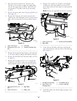
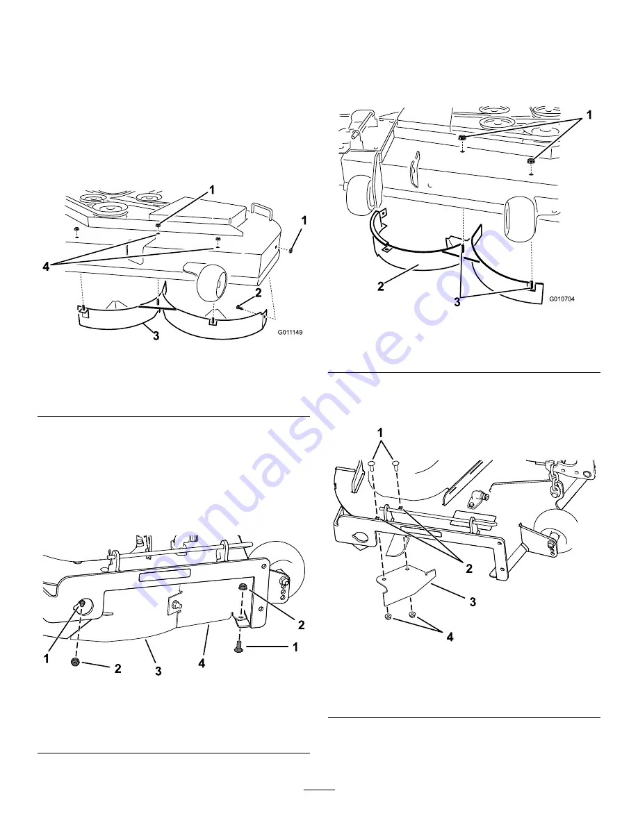
Remove the 2 locknuts (5/16 inch) secured to the
welded posts of the left baffle on the top of the mower
deck at the center and left of center positions (
G01
1149
1
1
2
3
4
g011149
Figure 30
1.
Locknut (5/16 inch)
3.
Left baffle
2.
Carriage bolt (5/16 x 3/4
inch)
4.
Install the fasteners here.
5.
Remove the carriage bolt and locknut on the side wall
of the mower deck securing the left baffle to the deck.
6.
Remove the left baffle from the mower deck as shown
in
.
7.
Remove the 2 carriage bolts (5/16 x 3/4 inch) and
2 locknuts (5/16 inch) securing the assembled right
baffle and baffle guard to the mower deck (
g191136
Figure 31
1.
Carriage bolt (5/16 x 3/4
inch)
3.
Right baffle
2.
Locknut (5/16 inch)
4.
Baffle guard
8.
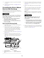
Remove the 2 locknuts (5/16 inch) to securing the
welded posts of the right baffle to the top of the
mower deck at the center and right of center positions
(
).
Note:
Remove the right baffle from the mower deck.
G010704
1
2
3
g010704
Figure 32
1.
Locknut (5/16 inch)
3.
Welded posts (right baffle)
2.
Right baffle
9.
Locate the cutoff baffle in the loose parts bag and
remove the fasteners at the rear holes of the discharge
plate (
).
g190734
Figure 33
1.
Carriage bolts (existing)
3.
Cutoff baffle (loose)
2.
Rear holes in the
discharge plate
4.
Locknuts (existing)
10.
Install the baffle at the side discharge opening on the
mower deck.
25
Summary of Contents for TimeCutter HD X5450
Page 55: ...Schematics g203461 Electrical Diagram Rev A 55 ...
Page 56: ...Notes ...
Page 57: ...Notes ...
Page 58: ...Notes ...

