g017618
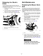
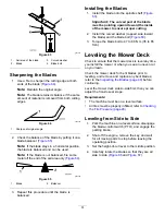
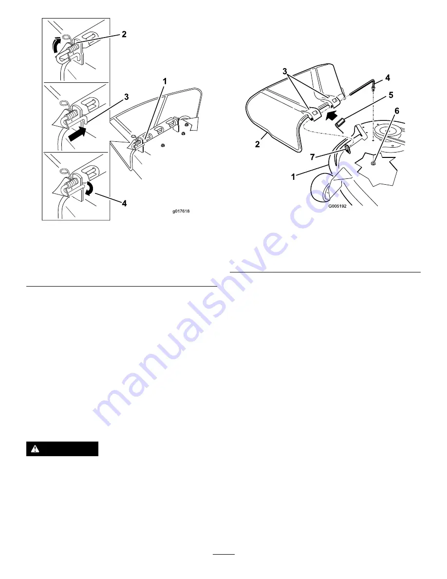
Figure 76
1.
Rod and spring assembly
installed
3.
Rod, short end, moved
behind mower bracket
2.
Loop end of the spring
installed into the notch in
the deflector bracket
4.
Short end, retained by
mower bracket.
7.
Secure the rod and spring assembly by twisting
it so the short end of the rod is placed behind
the front bracket welded to the deck (
).
Important:
The grass deflector must be
spring loaded in the down position. Lift the
deflector up to test that it snaps to the full
down position.
Replacing the Grass
Deflector
Machines with Stamped Mower
Decks Only
WARNING
An uncovered discharge opening could allow
the machine to throw objects toward you or
bystanders, resulting in serious injury. Also,
contact with the blade could occur.
Never operate the machine without the
grass deflector, the discharge cover, or the
grass-collection system in place.
Inspect the grass deflector for damage before each
use. Replace any damaged parts before use.
1.
Remove the nut (3/8 inch) from the rod under
the mower (
).
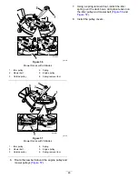
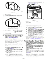
g005192
Figure 77
1.
Mower deck
5.
Spring
2.
Grass deflector
6.
Nut (3/8 inch)
3.
Grass-deflector bracket
7.
Short standoff
4.
Rod
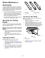
2.
Slide the rod out of the short standoff, the spring,
and the grass deflector (
).
3.
Remove the damaged or worn grass deflector.
4.
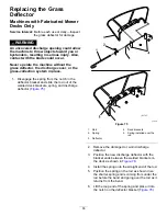
Replace the grass deflector (
5.
Slide the rod (straight end), through the
rear-grass-deflector bracket.
6.
Place the spring on the rod, with the end wires
down and between the grass deflector brackets.
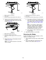
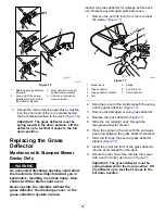
7.
Slide rod through the second grass-deflector
bracket (
).
8.
Insert the rod at the front of the grass deflector
into the short standoff on the deck.
9.
Secure the rear end of the rod into the mower
with a nut (3/8 inch) as shown in
.
Important:
The grass deflector must be
spring loaded and in the down position. Lift
the deflector up to test that it snaps to the
full down position.
56
Summary of Contents for TimeCutter 74726
Page 62: ...Schematics g028022 Electrical Diagram Rev A 62 ...
Page 63: ...Notes ...
Page 64: ......

