


Procedure for Reel Motor Case Drain Check:
1. Make sure hydraulic oil is at normal operating tem-
perature by operating the machine for approximately 10
minutes. Make sure the hydraulic tank is full.
2. Make sure machine is parked on a level surface with
the cutting units lowered. Make sure engine is off and
the parking brake is engaged.
CAUTION
Operate all hydraulic controls to relieve
system pressure and avoid injury from
pressurized hydraulic oil.
3. On suspected bad motor, clean hose connection
and disconnect hose from motor that returns to the man-
ifold (see table).
IMPORTANT: Make sure oil flow indicator arrow on
the flow gauge is showing that the oil will flow from
the motor through the tester and into the hose.
4. Install tester in series with the motor and the discon-
nected return hose. Make sure the flow control valve is
fully open.
5. Make sure backlap knob on the valve block is in the
mow position.
6. One person should sit on the seat and operate the
machine while another person reads the tester. Start en-
gine and move the throttle to full speed (3200
"
100
RPM).
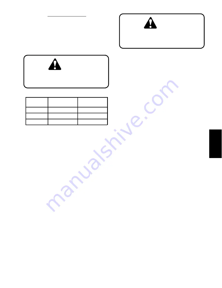
Motor
Position
Manifold Port
(Case Drain)
Manifold Port
(Motor Return)
Right Hand
D1
M1
Left Hand
D2
M3
Rear
D3
M6
CAUTION
Keep away from reels during test to pre-
vent personal injury from the rotating reel
blades.
7. Engage reels by pulling the knob on the instrument
panel out. While watching pressure gauges, slowly
close flow control valve until a pressure of 1200 PSI is
obtained.
8.
Disengage cutting units and stop engine.
9. Clean hose fitting and disconnect hose from case
drain on the manifold block (see table). Plug the man-
ifold port.
10. Put case drain hose into 1 quart container gra-
duated in ounces (1 liter container graduated in millili-
ters).
11. One person should sit on the seat and operate the
machine while another person holds the hose and reads
the tester. Start engine and move the throttle to full
speed (3200
"
100 RPM).
12. While sitting on seat, engage cutting units by pulling
the knob on the instrument panel out. Make sure gauge
pressure still reads 1200 PSI. After 15 seconds, push
knob on the instrument panel in to disengage cutting
units. Stop the engine.
13. Measure the amount of oil collected in the container.
Divide the number of ounces collected by 32 to get gal-
lons per minute. (Divide the number of milliliters col-
lected by 250 to get liters per minute).
14. Disconnect tester from motor and hose. Reconnect
hose to the pump.
15. Remove cap from manifold fitting. Reconnect case
drain hose to the motor.
16. If flow was greater than 0.7 GPM (2.6 LPM), repair
or replace the reel motor as necessary.
Hydraulic
System
Reelmaster 2300–D/2600–D
Page 4 – 33
Hydraulic System
Summary of Contents for REELMASTER 2300-D
Page 2: ...This page is blank ...
Page 4: ...This page is blank ...
Page 10: ...Safety Page 1 6 Reelmaster 2300 D 2600 D ...
Page 12: ...Equivalents and Conversions Product Records and Manuals Page 2 2 Reelmaster 2300 D 2600 D ...
Page 14: ...Maintenance Interval Chart Product Records and Manuals Page 2 4 Reelmaster 2300 D 2600 D ...
Page 38: ...Engine Page 3 20 Reelmaster 2300 D 2600 D ...
Page 158: ...Wheels and Brakes Page 6 8 Reelmaster 2300 D 2600 D ...
Page 185: ...This page is blank ...