background image

Maintenance

Lubricating the Machine

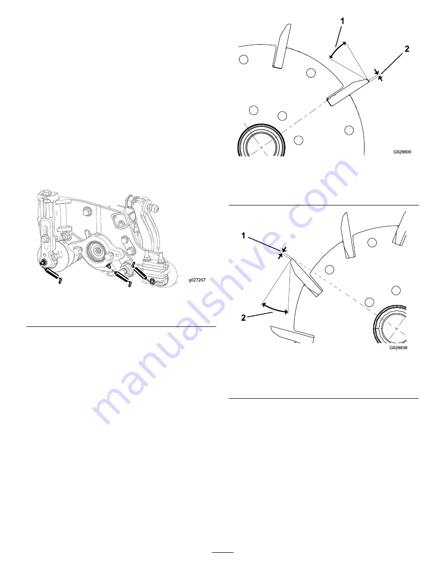
Regularly lubricate the 5 grease fittings of each cutting
unit (

Figure 22

with No. 2 lithium grease.

There are 2 lubrication points on the front roller, 2 on
the rear roller, and 1 at the reel-motor spline.

Note:

Lubricating the cutting units immediately

after washing helps purge water out of the
bearings and increases bearing life.

1.

Wipe each grease fitting with a clean rag.

2.

Apply grease until clean grease comes out of
the roller seals and the bearing relief valve.

3.

Wipe any excess grease away.

g027267

Figure 22

Grease fittings on the reel-motor side

Relief-Grinding the Reel

The reel has a land width of 1.3 to 1.5 mm (0.050 to
0.060 inch) and a 30-degree relief grind.

When the land width gets larger than 3 mm (0.120
inch) wide, do the following:

1.

Apply a 30 degree relief grind on all reel blades
until the land width is 1.3 mm (0.050 inch) wide
(

Figure 23

and

Figure 24

).

g028800

Figure 23

Models 03485 and 03487

1.

30 degrees

2.

1.3 mm (0.050 inch)

g028838

Figure 24

Models 03486 and 03488

1.

1.3 mm (0.050 inch)

2.

30 degrees

2.

Spin grind the reel to achieve <0.025 mm (0.001
inch) reel run-out.

Note:

This causes the land width to grow

slightly.

Note:

To extend the longevity of the sharpness of the

edge of the reel and the bedknife—after grinding the
reel and/or the bedknife—check the reel-to-bedknife
contact again after cutting 2 fairways, as any
burrs will be removed, which may create improper
reel-to-bedknife clearance and thus accelerate wear.

16


Summary of Contents for Reelmaster 03485

Page 1: ...nit Reelmaster 3550 or 3555 Series Traction Unit Model No 03485 Serial No 401370001 and Up Model No 03486 Serial No 401370001 and Up Model No 03487 Serial No 401400001 and Up Model No 03488 Serial No 401400001 and Up Register at www Toro com Original Instructions EN 3420 448 A ...

Page 2: ...ed g027162 Figure 1 1 Location of the model and serial numbers Model No Serial No This manual identifies potential hazards and has safety messages identified by the safety alert symbol Figure 2 which signals a hazard that may cause serious injury or death if you do not follow the recommended precautions g000502 Figure 2 1 Safety alert symbol This manual uses 2 words to highlight information Import...

Page 3: ...terial carefully Be familiar with the controls safety signs and the proper use of the equipment If the operator or mechanic cannot read the language of this manual it is the owner s responsibility to explain this material to them Become familiar with the safe operation of the equipment operator controls and safety signs The owner operator can prevent and is responsible for accidents that may cause...

Page 4: ... operator and are located near any area of potential danger Replace any decal that is damaged or missing decal93 6688 93 6688 1 Warning read the instructions before servicing or performing maintenance 2 Cutting hazard of hand or foot shut off the engine and wait for moving parts to stop 4 ...

Page 5: ...hine from the normal operating position 1 Inspecting the Cutting Unit Parts needed for this procedure 1 Cutting unit Procedure After the cutting unit is removed from the box inspect the following 1 Check each end of the reel for grease Note Grease should be visibly evident in the internal splines of the reel shaft 2 Ensure that all nuts and bolts are securely tightened 3 Make sure that the suspens...

Page 6: ...ield 4 Installing the Loose Parts Parts needed for this procedure 1 Straight grease fitting 1 O ring 2 Screws Procedure Install the grease fitting on the reel motor side of the cutting unit Use Figure 5 to determine the position of the reel motors g031275 Figure 5 1 Cutting unit 1 5 Cutting unit 5 2 Cutting unit 2 6 Reel motor 3 Cutting unit 3 7 Weight 4 Cutting unit 4 1 Remove and discard the set...

Page 7: ...4 Install the O ring on the reel motor Figure 7 g031254 Figure 7 1 O ring 5 Install the reel motor 6 Grease the side plate until excess grease comes out the grease vent Figure 6 7 ...

Page 8: ...dknife and their interaction After completing this procedure always test the cutting unit performance under your field conditions You may need to make further adjustments to obtain optimal cutting performance Important Do not overtighten the bedknife to the reel or you will damage it After backlapping the cutting unit or grinding the reel you may need to mow with the cutting unit for a few minutes...

Page 9: ...t as necessary to get light drag on the shim between the same blade and bedknife 10 Repeat steps 8 and 9 until the shim can be slid through both gaps with slight drag but 1 click in on both sides prevents the shim from passing through on both sides Note The bedknife is now parallel to the reel Note This procedure should not be needed on daily adjustments but should be done after grinding or disass...

Page 10: ...oil conditions The cutting unit setup aggressiveness of cut rollers bedknives attachments installed turf compensation settings etc will also affect the effective height of cut Check the effective height of cut using the Turf Evaluator Model 04399 regularly to determine the desired bench set height of cut Aggressiveness of Cut The aggressiveness of cut has a significant impact on the performance of...

Page 11: ...arm chain is attached determines the pitch angle of the rear roller Figure 14 g027264 Figure 14 1 Bottom hole 3 Lift chain 2 U backet Groomer These are the recommended height of cut settings when a groomer kit is installed on the cutting unit 11 ...

Page 12: ...2 86 cm 1 125 inches Less Normal More 4 5 6 4 3 3 3 18 cm 1 250 inches Less Normal More 4 5 6 4 3 3 3 49 cm 1 375 inches Less Normal More 4 5 6 4 3 3 3 81 cm 1 500 inches Less Normal More 5 6 7 3 3 3 Indicates that the U bracket on lift arm is positioned in the bottom hole Figure 14 High HOC Kit Part 137 0890 must be installed Front HOC bracket must be positioned in the top side plate hole Y indic...

Page 13: ...e between the bottom of the screw head and the face of the bar to determine the height of cut 4 Hook the screw head on the cutting edge of the bedknife and rest the rear end of the bar on the rear roller Figure 17 5 Rotate the adjusting screw until the front roller contacts the gauge bar Figure 17 Adjust both ends of the roller until the entire roller is parallel to the bedknife g027266 Figure 17 ...

Page 14: ... 3 mm 0 370 inch 12 7 to 38 1 mm 0 500 to 1 50 inches Warm season grasses may require the Low HOC bedknife for 12 7 mm 0 500 inch and below g006510 Figure 18 1 Bedknife lip height Adjusting the Turf Compensation Settings The turf compensation spring transfers the weight from the front to the rear roller This helps to reduce a wave pattern in the turf also known as marcelling or bobbing Important M...

Page 15: ...nd bedknife perpendicular to the bedknife Figure 20 Slowly rotate the reel forward it should cut the paper g027166 Figure 20 Note If excessive contact reel drag is evident it will be either necessary to backlap reface the front of the bedknife or grind the cutting unit to achieve the sharp edges needed for precision cutting Refer to the Toro Manual for Sharpening Reel and Rotary Mowers Form No 091...

Page 16: ...th of 1 3 to 1 5 mm 0 050 to 0 060 inch and a 30 degree relief grind When the land width gets larger than 3 mm 0 120 inch wide do the following 1 Apply a 30 degree relief grind on all reel blades until the land width is 1 3 mm 0 050 inch wide Figure 23 and Figure 24 g028800 Figure 23 Models 03485 and 03487 1 30 degrees 2 1 3 mm 0 050 inch g028838 Figure 24 Models 03486 and 03488 1 1 3 mm 0 050 inc...

Page 17: ... inch 4 8 mm 0 190 inch 10 10 degrees EdgeMax Model 03484 Model 03486 137 0831 18 inch 137 0833 22 inch 6 9 mm 0 270 inch 4 8 mm 0 190 inch 10 5 degrees Standard Optional 121 3166 18 inch 108 9096 22 inch 6 9 mm 0 270 inch 4 8 mm 0 190 inch 10 5 degrees Heavy Duty Optional 110 4074 22 inch 9 3 mm 0 370 inch 4 8 mm 0 190 inch 10 5 degrees Recommended Top and Front Bedknife Grind Angles Figure 25 g0...

Page 18: ...le that your grinder produces and should be within 2 degrees of the recommended top grind angle Servicing the Bedbar Removing the Bedbar 1 Turn the bedbar adjusting screws counterclockwise to back the bedknife away from the reel Figure 29 g027175 Figure 29 1 Bedbar adjusting screw 3 Washer 2 Bedbar 4 Spring tension nut 2 Back out the spring tension nut until the washer is no longer tensioned again...

Page 19: ...sher onto the adjuster shaft and slide the adjuster shaft into the flange bushings in the frame of the cutting unit Figure 33 5 Secure the adjuster shaft with a flat washer and a locknut Figure 33 Torque the locknut to 20 to 27 N m 15 to 20 ft lb Note The bedbar adjuster shaft has left hand threads 6 Apply anti seize compound to the threads of the bedbar adjuster screw that fits into the adjuster ...

Page 20: ...haft adjuster 4 Apply anti seize compound here 7 Apply anti seize compound here 10 Compression spring 2 Wave washer 5 Flat washer 8 Bedbar adjuster screw 11 Spring tension nut 3 Flange bushing 6 Locknut 9 Hardened washer 20 ...

Page 21: ...rebuild a roller The Roller Rebuild Tool Kit includes all the tools and the installation instructions required to rebuild a roller with the Roller Rebuild Kit Refer to your Parts Catalog or contact your distributor for assistance g007790 Figure 34 1 Rebuild kit Part No 114 5430 6 Bearing nut 2 Rebuild tool kit Part No 115 0803 7 Inner seal tool 3 Inner seal 8 Washer 4 Bearing 9 Bearing outer seal ...

Page 22: ... CU 3500 SERIES Cutting unit 2006 42 EC 03488 401370001 and Up 22 inch 11 Blade DPA Cutting Unit Reelmaster 3550 or 3555 Series Traction Unit 22IN 5IN 11 BLD FSR DPA CU 3500 SER Cutting unit 2006 42 EC Relevant technical documentation has been compiled as required per Part B of Annex VII of 2006 42 EC We will undertake to transmit in response to requests by national authorities relevant informatio...

Page 23: ...f these activities We will not sell your personal information to any other company We reserve the right to disclose personal information in order to comply with applicable laws and with requests by the appropriate authorities to operate our systems properly or for our own protection or that of other users Retention of your Personal Information We will keep your personal information as long as we n...

Page 24: ...to damage to seats due to wear or abrasion worn painted surfaces scratched decals or windows etc Parts Parts scheduled for replacement as required maintenance are warranted for the period of time up to the scheduled replacement time for that part Parts replaced under this warranty are covered for the duration of the original product warranty and become the property of Toro Toro will make the final...

Reviews: