background image

16

Changing Engine Oil and Filter

Change oil initially after the first 5 hours of operation,

thereafter change oil every 100 hours and filter every 200

hours.

1.

Park the machine on a level surface and turn the engine

off.

2.

Remove drain plug and let oil flow into drain pan.

When oil stops, install drain plug.

Note:

 Warm oil flows better and carries more contaminants

than cold oil.

3.

Remove oil filter. Apply a light coat of clean oil to the

new filter gasket.

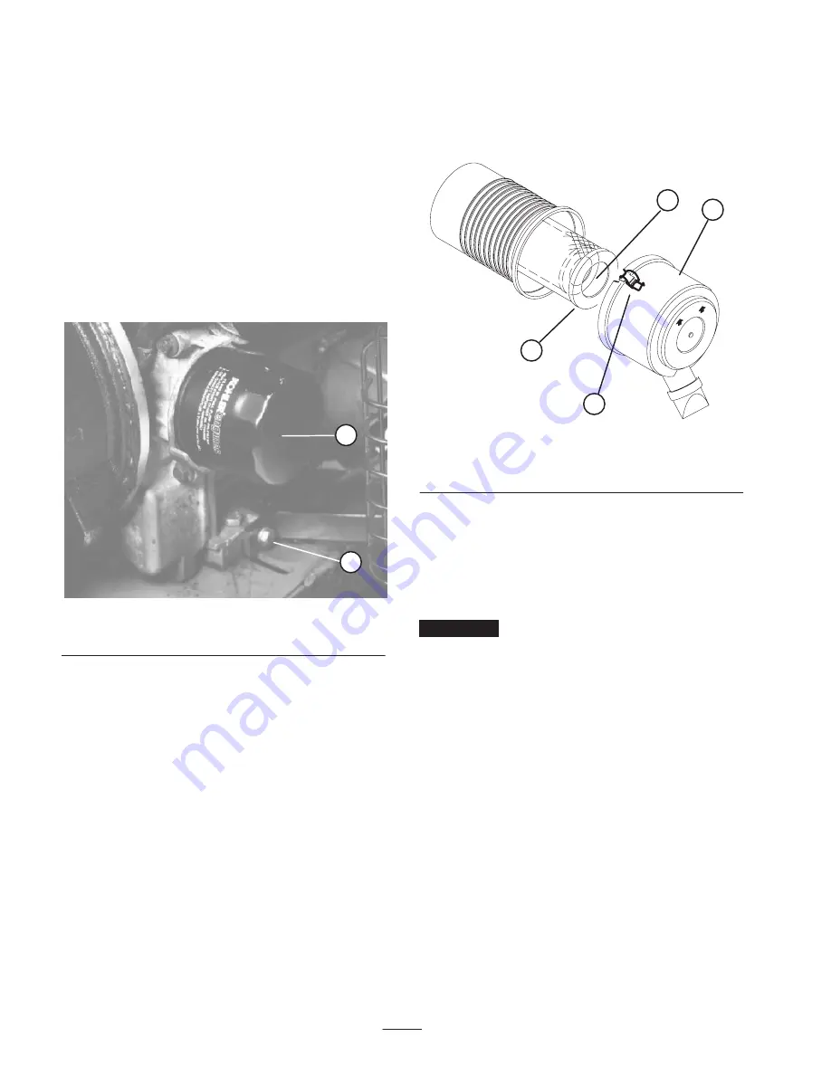
1

2

Figure 18

1. Drain plug

2. Oil filter

4.

Screw filter on by hand until gasket contacts mounting

plate, then tighten 1/2 turn further. DO NOT

OVER–TIGHTEN.

5.

Add oil to crankcase, refer to Check Engine Oil.

6.

Dispose of used oil properly.

General Air Cleaner

Maintenance

Check air cleaner body for damage which could

possibly cause an air leak. Replace a damaged air

cleaner body.

Service the air cleaner filters every 400 hours (more

frequently in extreme dusty or dirty conditions). Do not

over service air filter.

Be sure cover is sealing around air cleaner body.

Servicing Air Cleaner

1.

Release latches securing air cleaner cover to air cleaner

body. Separate cover from body. Clean inside of air

cleaner cover.

2

ÎÎ

ÎÎ

ÎÎÎ

ÎÎÎ

ÎÎÎ

ÎÎ

ÎÎ

ÎÎ

ÎÎ

1

3

4

Figure 19

1. Air cleaner latches
2. Dust cup

3. Primary filter
4. Safety filter

2.

Gently slide primary filter out of air cleaner body to

reduce the amount of dust dislodged. Avoid knocking

filter against air cleaner body. 

Do not remove safety

filter.

3.

Inspect primary filter and discard if damaged. Do not

wash or reuse a damaged filter.

Important


Never attempt to clean a safety filter.

Replace the safety filter with a new one after every

three primary filter services.

4.

Blow compressed air from inside to the outside of dry

filter element. Do not exceed 100 psi to prevent damage

to the element.

5.

Keep air hose nozzle at least 2” from filter and move

nozzle up and down while rotating the filter element.

Inspect for holes and tears by looking through the filter

toward a bright light.

6.

Inspect new filter for shipping damage. Check sealing

end of filter. Do not install a damaged filter.

7.

Insert new filter properly into air cleaner body. Make

sure filter is sealed properly by applying pressure to

outer rim of filter when installing. Do not press on

flexible center of filter.

8.

Reinstall cover and secure latches. Make sure cover is

positioned with TOP side up.

Summary of Contents for RAKE-O-VAC 07050

Page 1: ...Operator s Manual Domestic English EN Form No 3362 316 Rev A 66 Rake O Vac Sweeper Model No 07050 240000201 and up...

Page 2: ...cations 7 Dimensions and Weights approx 7 Optional Equipment 7 Setup 8 Remove Activate And Charge Battery 8 Install Battery 8 Mount Sweeper To Prime Mover 9 Removing Sweeper From Prime Mover 9 Page Be...

Page 3: ...nd accident prevention partially are dependent upon the design and configuration of the machine these factors are also dependent upon the awareness concern and proper training of the personnel involve...

Page 4: ...operator position Shift into neutral stop prime mover and engage parking brake Shut engine off and wait for all movement to stop The impeller may momentarily turn after other components have stopped U...

Page 5: ...acturers could be dangerous Such use could void the product warranty of The Toro Company Safety and Instruction Decals Safety decals and instructions are easily visible to the operator and are located...

Page 6: ...6 92 8309 93 4041...

Page 7: ...min at 3250 engine R P M Hopper 5 3 4 cu yd volume 18 gauge top section with 16 gauge bottom section rib reinforced full width self cleaning semi automatic dumping Flex Tip Reel Forward spinning with...

Page 8: ...fill each cell until electrolyte is up to fill line 4 Replace filler caps and connect a 3 to 4 amp battery charger to the battery posts Charge the battery at a rate of 3 to 4 amperes for 4 to 8 hours...

Page 9: ...r jack caster wheel onto sweeper end of jack tube 3 Adjust sweeper jack so distance from top of frame to ground is approximately 23 1 2 Fig 2 4 Back prime mover up to sweeper 5 Adjust sweeper hitch to...

Page 10: ...onditions 5 Install the dipstick firmly in place Fill Fuel Tank Fuel tank capacity is approximately 4 gallons Danger In certain conditions gasoline is extremely flammable and highly explosive A fire o...

Page 11: ...ine 1 Figure 5 1 Transport hook 2 When transporting sweeper from one location to another support flex tip reel broom or thatching reel with transport hooks Adjust Reel Support Arm When machine is oper...

Page 12: ...operating the contact width surface should be about 1 wide across entire length of broom 1 Figure 8 1 Depth adjusting bolt 4 Repeat procedure on opposite side of machine 5 Retighten adjustment lock nu...

Page 13: ...N position After engine starts regulate choke to keep engine running smoothly As soon as possible open the choke by moving lever to the OFF position Starting a warm engine requires little or no chokin...

Page 14: ...gs clippings leaves pine needles and cones small debris beverage cans small bottles paper plates etc The rake teeth are made of flexible nylon and easily changed To prevent damage the rake is protecte...

Page 15: ...n operating conditions are extremely dusty and dirty Dusty and dirty operating conditions could cause dirt to get into the bearings and bushings resulting in accelerated wear The grease fittings that...

Page 16: ...air cleaner cover to air cleaner body Separate cover from body Clean inside of air cleaner cover 2 1 3 4 Figure 19 1 Air cleaner latches 2 Dust cup 3 Primary filter 4 Safety filter 2 Gently slide pri...

Page 17: ...ake sure the grass screen cooling fins and other external surfaces of the engine are kept clean at all times Every 100 hours of operation more often under extremely dusty dirty conditions remove the b...

Page 18: ...other access plate Adjusting Belts Check condition and tension of belts after first day of operation and every 200 operating hours thereafter Impeller Drive Belt 1 Check tension by depressing belt at...

Page 19: ...as too much slack loosen idler pulley nut press forward on idler pulley until desired tension is obtained and retighten idler pulley nut If belt is too tight loosen idler pulley nut pull rearward on i...

Page 20: ...drive belt Fig 29 4 Remove 2 capscrews lockwashers and nuts securing reel shaft bearings to reel support arms on each side of sweeper Lower flex tip reel to the ground 5 Lift reel support arms to the...

Page 21: ...Clevis 13 Reassemble jam nut and adjusting screw with spacer positioned on adjusting screw between pivot block and clevis This is the storage position for spacer during thatcher operation 14 Repeat pr...

Page 22: ...ed end of tine and fasten securely with capscrew and lockwasher Brush Half Replacement 1 Remove brush from sweeper 2 Loosen clamps with a allen wrench and remove from brush halves 1 Figure 35 1 Clamp...

Page 23: ...ct CALIFORNIA Proposition 65 Warning Battery posts terminals and related accessories contain lead and lead compounds chemicals known to the State of California to cause cancer and reproductive harm Wa...

Page 24: ...is not limited to dam age to seats due to wear or abrasion worn painted surfaces scratched decals or windows etc Parts Parts scheduled for replacement as required maintenance are war ranted for the p...

Reviews: