background image

3

Page

Matching the Height of Cut

47

. . . . . . . . . . . . . . . . . 

Replacing the Mower Belt

48

. . . . . . . . . . . . . . . . . . 

Replacing the PTO Drive Belt

48

. . . . . . . . . . . . . . . 

Replacing the Caster Wheel Fork Bushings

49

. . . . 

Caster Wheel and Bearings Service

50

. . . . . . . . . . . 

Replacing the Grass Deflector

50

. . . . . . . . . . . . . . . 

Wiring Diagram

51

. . . . . . . . . . . . . . . . . . . . . . . . . . 

Hydraulic Diagram

52

. . . . . . . . . . . . . . . . . . . . . . . . 

Cleaning and Storage

53

. . . . . . . . . . . . . . . . . . . . . . 

Troubleshooting

53

. . . . . . . . . . . . . . . . . . . . . . . . . . . . . 

The Toro Total Coverage Guarantee

56

. . . . . . . . . . . . . 

Introduction

Read this manual carefully to learn how to operate and
maintain your product properly. The information in this
manual can help you and others avoid injury and product
damage. Although Toro designs and produces safe
products, you are responsible for operating the product
properly and safely.

Whenever you need service, genuine Toro parts, or
additional information, contact an Authorized Service
Dealer or Toro Customer Service and have the model and
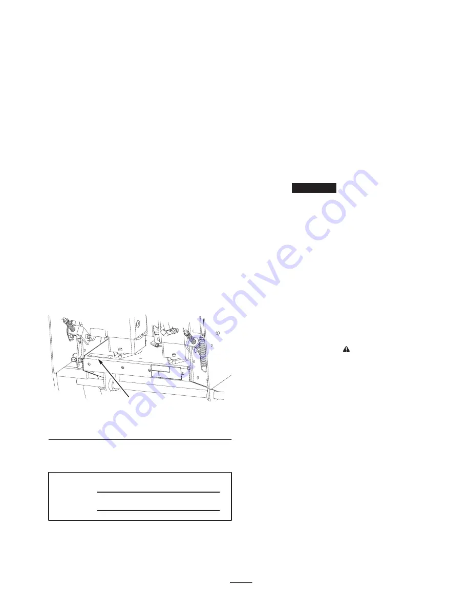
serial numbers of your product ready. Figure 1 illustrates
the location of the model and serial numbers on the
product.

1

m–6612

Figure 1

1.

Location of the model and serial numbers

Write the product model and serial numbers in the space
below:

Model No.

Serial No.

This manual identifies potential hazards and has special
safety messages that help you and others avoid personal
injury and even death. DangerWarning, and Caution are
signal words used to identify the level of hazard.
However, regardless of the hazard, be extremely careful.

Danger signals an extreme hazard that will cause serious
injury or death if you do not follow the recommended
precautions.

Warning signals a hazard that may cause serious injury or
death if you do not follow the recommended precautions.

Caution signals a hazard that may cause minor or
moderate injury if you do not follow the recommended
precautions.

This manual uses two other words to highlight
information. 

Important

 calls attention to special

mechanical information and Note: emphasizes general
information worthy of special attention.

Safety

This machine meets or exceeds the B71.4–1999
specifications of the American National Standards
Institute in effect at the time of production.

Note: The addition of attachments made by other
manufacturers that do not meet American National
Standards Institute certification will cause noncompliance
of this machine.

Improper use or maintenance by the operator or owner
can result in injury. To reduce the potential for injury,
comply with these safety instructions and always pay
attention to the safety alert 

 symbol, which means

CAUTION, WARNING, or DANGER—“personal
safety instruction.” Failure to comply with the
instruction may result in personal injury or death.

Safe Operating Practices

The following instructions are from ANSI standard
B71.4—1999.

Training

Read the Operator’s Manual and other training
material. If the operator(s) or mechanic(s) can not read
English it is the owner’s responsibility to explain this
material to them.

Become familiar with the safe operation of the
equipment, operator controls, and safety signs.

All operators and mechanics should be trained. The
owner is responsible for training the users.

Summary of Contents for ProLine Hydro

Page 1: ...rator s Manual Original Instructions EN Register your product at www Toro com Form No 3350 745 Mid Size Mower ProLine Hydro 15 HP with 44in Side Discharge Mower Model No 30439 Serial No 240000001 and...

Page 2: ...acket 14 Installing the Handle Assembly 14 Installing the Fuel Tank 15 Installing the Control Rods 16 Installing the Speed Control Rod 17 Page Installing the Hairpin Cotter Pins and Spacers 17 Checkin...

Page 3: ...death if you do not follow the recommended precautions Warning signals a hazard that may cause serious injury or death if you do not follow the recommended precautions Caution signals a hazard that ma...

Page 4: ...aution when making turns and when changing directions on slopes Never raise deck with the blades running Never operate with the PTO shield or other guards not securely in place Be sure all interlocks...

Page 5: ...oved attachments Check carefully for overhead clearances i e branches doorways electrical wires before operating under any objects and do not contact them Slope Operation All slopes and ramps require...

Page 6: ...6...

Page 7: ...7 Slope Chart Fold along appropriate line Align this edge with a vertical surface Tree Building Fence post pole etc Example Compare slope with folded edge...

Page 8: ...8...

Page 9: ...cals Safety decals and instructions are easily visible to the operator and are located near any area of potential danger Replace any decal that is damaged or lost 1 523552 43 8480 66 1340 67 5360 68 8...

Page 10: ...10 98 4387 1 Warning wearhearing protection 104 8186 104 2838 104 8569 105 4110 105 4146 106 5532 106 0699 106 5513 105 4109...

Page 11: ...p debris before operating 5 Cutting of hand or foot mower 6 Engine stop 7 Engine run 8 Hour meter 9 To drive forward move the controls as illustrated 10 To place the machine in neutral move the contro...

Page 12: ...t possible then refuel such equipment on a truck or trailer from a portable container rather than from a gasoline dispenser nozzle If a gasoline dispenser nozzle must be used keep the nozzle in contac...

Page 13: ...5 16 inch Spring Hose clamp 1 2 2 2 4 2 1 Installing the fuel tank 4 E ring 2 Installing the control rods 5 Washer Cotter pin 1 1 Installing the speed control rod 6 Hairpin cotter pin Spacer 2 6 Inst...

Page 14: ...nter gage wheels with the previously removed bolt small washer and nut Fig 3 1 2 3 4 4 m 6510 Figure 3 1 Center Gage Wheels and Spacer 2 Nut 3 Bolt 4 Washer Step 2 Installing the Handle Assembly Parts...

Page 15: ...e Fuel Tank Parts needed for this step Qty Part 1 Fuel tank with studs installed 2 Bolt 5 16 X 7 8 inch 2 Lock nut 5 16 inch 4 Washer 5 16 inch 1 Hose clamp 2 Lock washer 5 16 inch 2 Spring Procedure...

Page 16: ...ocknut one full turn This will allow the spring to work 5 4 3 2 1 3 7 6 m 6583 Figure 7 1 Bolt 5 8 x 7 8 inch 2 Lock washer 5 16 inch 3 Washer 5 16 inch 4 Spring 5 Locknut 6 Hose clamp 7 Fuel tank con...

Page 17: ...d secure it with a washer and cotter pin Fig 10 Note If necessary move the speed control lever until the swivel will go into the speed control crank m 6602 1 2 3 4 5 3 6 Figure 10 1 Speed control rod...

Page 18: ...Refer to page 33 for the correct correct tire pressure Step 8 Checking the Hydraulic Fluid and Engine Oil Parts needed for this step None Procedure Check the hydraulic fluid level before the engine is...

Page 19: ...Presence Control OPC levers OPC levers are used in conjunction with deck engagement switch PTO to release blade brake and engage clutch to drive mower blades Release OPC levers to disengage mower bla...

Page 20: ...tarter handle firmly and pull out until positive engagement results then pull handle vigorously to start engine and allow rope to recoil slowly Important Do not pull recoil rope to its limit or let go...

Page 21: ...ge 42 Children or bystanders may be injured if they move or attempt to operate the machine while it is unattended Always remove the ignition key and set the parking brake when leaving the machine unat...

Page 22: ...ot operate as described have an Authorized Service Dealer repair the safety system immediately 1 Set the neutral locks and place speed control lever in neutral Start the engine refer to Starting and S...

Page 23: ...if it is left unattended Note Remember to remove the key from the ignition switch if you leave the machine Children or bystanders may be injured if they move or attempt to operate the machine while it...

Page 24: ...ause injury or death Never remove the grass deflector from the mower because the grass deflector routes material down toward the turf If the grass deflector is ever damaged replace it immediately Neve...

Page 25: ...tion for each height of cut position There needs to be 3 8 inch 10 mm minimum clearance above the ground 1 After adjusting height of cut check the gage wheels so that there is a minimum of 3 8 inch 10...

Page 26: ...uring handle to rear frame Fig 27 5 Pivot handle to desired operating position and install lower flange bolts 3 8 x 1 inch and flange nuts into mounting holes Tighten all flange bolts m 6600 7 8 9 2 1...

Page 27: ...40 Hours Tires check pressure PTO Belt Idler Arm grease Hydraulic Oil check 50 Hours Belts check for wear cracks Paper Air Cleaner clean1 100 Hours Engine Oil change1 Spark Plug s check Electric Clutc...

Page 28: ...isengage the PTO and set the parking brake 2 Stop the engine remove the key and wait for all moving parts to stop before leaving the operating position 3 Clean around the air cleaner to prevent dirt f...

Page 29: ...e 2 Disengage the PTO and set the parking brake 3 Stop the engine remove the key and wait for all moving parts to stop before leaving the operating position 4 Clean around the oil dipstick Fig 29 so t...

Page 30: ...dditional 3 4 turn Fig 31 5 Fill the crankcase with the proper type of new oil refer to Servicing the Engine Oil page 29 6 Run the engine for about 3 minutes stop the engine and check for oil leaks ar...

Page 31: ...s to 16 ft lb 22 N m 3 Connect the wires to the spark plugs Fig 32 Cleaning the Cooling System Clean the air intake screen from grass and debris before each use Check and clean cooling fins and engine...

Page 32: ...he fitting s 4 Connect a grease gun to the fitting Pump grease into the fittings until grease begins to ooze out of the bearings 5 Wipe up any excess grease Where to add Grease Lubricate the grease fi...

Page 33: ...s on flange studs Fig 41 2 Check adjustment by inserting feeler gauge thru slots next to studs Fig 41 3 The proper disengaged clearance between the clutch plates is 0 012 0 024 inch 0 30 0 60 mm It wi...

Page 34: ...l shut off valve at fuel tank Fig 42 4 Squeeze the ends of the hose clamps together and slide them away from the filter Fig 43 5 Remove the filter from the fuel lines 6 Install a new filter and move t...

Page 35: ...stem Make sure all hydraulic fluid hoses and lines are in good condition and all hydraulic connections and fittings are tight before applying pressure to hydraulic system Warning Replacing the Hydraul...

Page 36: ...ks loose fittings kinked lines loose mounting supports wear weather and chemical deterioration Make necessary repairs before operating Note Keep areas around hydraulic system clean from grass and debr...

Page 37: ...tion Fig 48 7 Tighten the nuts on both sides of the swivel Fig 48 m 6607 4 3 5 12 3 6 9 Side View 2 2 4 1 1 Figure 48 1 Speed control rod 2 Nut 3 Speed control crank 4 Tabs in 6 o clock position 5 Swi...

Page 38: ...ge adjustments can be performed Contact with moving parts or hot surfaces may cause personal injury Keep hands feet face clothing and other body parts away from rotating parts muffler and other hot su...

Page 39: ...sure the speed control lever is in the neutral position and the tire does not rotate 10 Repeat adjustment if needed 3 2 m 6604 1 Figure 52 1 Hydro control linkage 2 Front nut 3 Rear adjusting nut Note...

Page 40: ...d Electrical system will not perform proper safety shut off with Operator Presence Control OPC levers taped or fastened in the engaged position Make sure Operator Presence Control OPC levers are worki...

Page 41: ...n or the engine will kill 2 Move the respective drive lever upward until it reaches the neutral position and engage neutral locks 3 If the tire rotates in either direction the length of the control ro...

Page 42: ...brake handle should be close to the 1 o clock position 5 If there is a reasonable amount of force no adjustment is required Adjusting the Brake The brake handle is on the left side of machine Fig 59 I...

Page 43: ...Fig 60 If you notice any damage wear or a slot forming in this area item 3 in Fig 60 immediately install a new blade 1 2 3 m 151 Figure 60 1 Cutting Edge 2 Curved Area 3 Wear slot Forming Checking for...

Page 44: ...balanced 1 2 m 1855 Figure 65 1 Blade 2 Balancer Installing the Blades 1 Install the blade onto the spindle shaft Fig 63 Important The sail part of the blade must be pointing upward toward the inside...

Page 45: ...before leaving the operating position 3 Adjust the tire pressure in all tires to specifications on page 33 4 Measure engine deck height at location A Fig 67 5 Measure engine deck height at location B...

Page 46: ...tions A and B 5 Caster spacers Checking the Deck Front to Rear Pitch 1 Check the tire pressure on both deck and traction unit 2 Position one blade front to rear Fig 70 Measure at C and D locations Fig...

Page 47: ...h 6 mm A Front B m 1078 Figure 73 MEASURE FROM CUTTING EDGE TO A LEVEL SURFACE m 2550 Figure 74 Changing the Side to Side Leveling Changing the side to side leveling is done by adjusting tire pressure...

Page 48: ...de an 1 8 inch 3 mm from belt Fig 77 10 Reinstall the deck covers onto the cutting unit then reinstall and tighten the knobs 11 Install the carrier frame cover onto the cutting unit then install and t...

Page 49: ...rect installation and to maintain a level deck 4 2 1 3 2 m 6372 Figure 79 1 Locking Pin 2 Spacers locate as required 3 Carrier frame mounting tube 4 Caster wheel fork 4 Insert a pin punch into the mou...

Page 50: ...heel bolt and locknut Tighten the locknut until the spanner bushing bottoms against the inside of the caster forks Fig 81 7 Grease the fitting on the caster wheel Replacing the Grass Deflector An unco...

Page 51: ...10A F1 BU BN BK RED PINK Y D1 Y BK BK 1 2 5 4 7 8 PK TAN PK Y GREY W GREEN VIO K1 Interlock Relay Clutch PTO Switch Off KEY SWITCH ORANGE T BLACK WIRE COLOR CODES BROWN R PK 2 3 5 4 1 Operator Presen...

Page 52: ...52 Hydraulic Diagram A B A B Motor Right Side Motor Left side Pump Right Side Pump Left side Expansion Tank Filter Charge Pump Inlet Case Drain m 5225...

Page 53: ...ot start again Use the primer if equipped on machine several times to ensure no fuel remains in primer system G Dispose of fuel properly Recycle as per local codes Important Do not store stabilizer co...

Page 54: ...low 2 Add oil to crankcase 3 Cooling fins and air passages under engine blower housing are plugged 3 Remove obstruction from cooling fins and air passages Machine does not drive 1 Neutral lock is in n...

Page 55: ...arpen blade s g g 2 Cutting blade s is are bent 2 Install new cutting blade s 3 Mower is not level 3 Level mower from side to side and front to rear 4 Underside of mower is dirty 4 Clean the underside...

Page 56: ...ered There is no other express warranty except for special emission system coverage on some products This express warranty does not cover the following Cost of regular maintenance service or parts suc...

Reviews: