Controls System
Maintenance
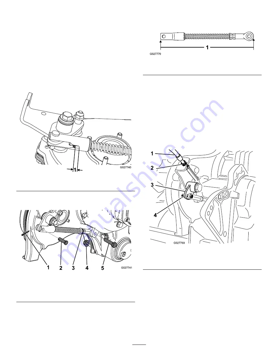
Adjusting the Traction Control
If the traction control does not engage or slips during
operation, the traction control may need adjusting.
1.
Move the traction control to the Engaged position.
2.
Measure the distance from the roll pin to the end of the
slot (
Figure 46
); if it is less than 0.8 mm (1/32 inch),
adjust the clutch according to the steps below.
Figure 46
1.
Measure this distance
3.
Remove the cotter pin, clevis pin, nut, and bolt securing
the bell-crank link assembly to the machine (
Figure 47
).
Figure 47
1.
Cotter pin
4.
Nut
2.
Clevis pin
5.
Bolt
3.
Jam nut
4.
Loosen the jam nut and adjust the bell-crank link
assembly until it measures 24 cm (9.5 inches) from end
to end (
Figure 48
).
1
G027770
Figure 48
1.
24 cm (9.5 inches)
5.
Tighten the jam nut and install the bell-crank link
assembly using the previously removed hardware
(
Figure 47
).
6.
Engage the traction control lever and measure the
distance between the roll pin and the end of the slot
(
Figure 46
). The distance should be between 6 mm
(1/4 inch) to 9.5 mm (3/8 inch).
Note:
If the distance is not in this range, adjust
the jam nuts on the traction clutch cable near the
transmission bulkhead (
Figure 49
) or the control-panel
bulkhead (
Figure 50
).
G027769
4
3
2
1
Figure 49
1.
Traction control cable
3.
Bell crank
2.
Jam nuts
4.
Clevis pin & cotter pin
33


