Toro Greensmaster 3120 Operator'S Manual Download Page 27

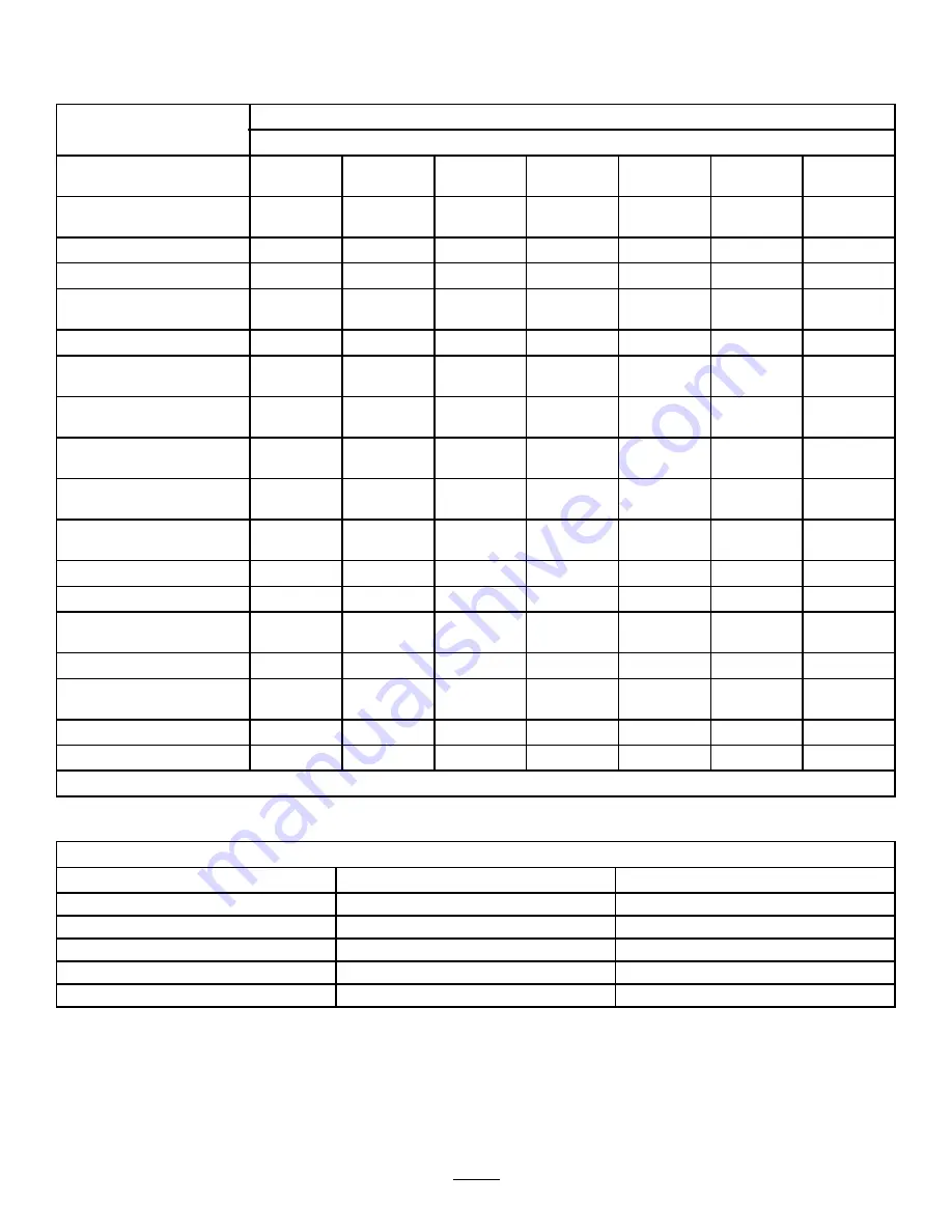
Daily Maintenance Checklist

Duplicate this page for routine use.

For the week of:

Maintenance Check Item

Mon.

Tues.

Wed.

Thurs.

Fri.

Sat.

Sun.

Check the safety-interlock
operation.

Check the instrument
operation

Check the brake operation.

Check the fuel level.

Check the hydraulic-fluid
level.

Check the engine-oil level.

Clean the engine-air-cooling
fins.

Inspect the air-filter
pre-cleaner.

Check any unusual engine
noises.

Check the reel-to-bedknife
adjustment.

Check the hydraulic hoses
for damage.

Check for fluid leaks.

Check the tire pressure.

Check the height-of-cut
adjustment.

Lubricate all grease fittings.

1

Lubricate the mow, lift, and
brake linkage.

Touch-up damaged paint.

Wash the machine.

1. Immediately after every washing, regardless of the interval listed.

Notation for Areas of Concern

Inspection performed by:

Item

Date

Information

27


Summary of Contents for Greensmaster 3120

Page 1: ...Form No 3428 574 Rev A Greensmaster 3120 2 Wheel Drive Traction Unit Model No 04355 Serial No 403410001 and Up Register at www Toro com Original Instructions EN 3428 574 A...

Page 2: ...turf Using this product for purposes other than its intended use could prove dangerous to you and bystanders Read this information carefully to learn how to operate and maintain your product properly...

Page 3: ...hecklist 27 Pre Maintenance Procedures 28 Removing the Seat Assembly 28 Raising the Machine 28 Lubrication 29 Greasing the Machine 29 Lubricating the Pivot Points 30 Engine Maintenance 30 Engine Safet...

Page 4: ...hut off the engine remove the key if equipped and wait for all movement to stop before you leave the operator s position Allow the machine to cool before adjusting servicing cleaning or storing it Imp...

Page 5: ...gine start 3 Engine shut off decal105 8306 105 8306 1 Forward machine speeds 3 Slow use for mowing 2 Fast use for transport 4 Neutral use for backlapping decal115 8226 115 8226 1 Tipping hazard read t...

Page 6: ...ing engage the parking brake shut off the engine and remove the key before leaving the machine decalbatterysymbols Battery Symbols Some or all of these symbols are on your battery 1 Explosion hazard 6...

Page 7: ...8 Fast 3 Off 9 Front and rear lights 4 Choke 10 Lights off 5 On 11 Front lights 6 Slow decal139 2724 139 2724 decal137 9706 137 9706 1 Cutting hazard of the hand or foot shut off the engine remove th...

Page 8: ...or 3 4 Grass basket 3 Install the cutting units 5 No parts required Mark the outer grass baskets Rear Weight Kit Part No 100 6441 purchase separately 1 6 19 5 kg 43 lb of calcium chloride purchase sep...

Page 9: ...4 5 Connect a 2 to 4 A battery charger to the battery posts Charge the battery for at least 2 hours at 4 A or for at least 4 hours at 2 A until the specific gravity is 1 250 or higher and the temperat...

Page 10: ...allow the battery terminals to touch any metal parts of the machine Do not allow metal tools to short between the battery terminals and metal parts of the machine g032706 Figure 5 1 Negative 3 Battery...

Page 11: ...can result in you being thrown from the seat and injured during a rollover accident Always use the seat belt 4 Installing the Cutting Units For Cutting Unit Models 04610 04611 04616 04618 04619 04624...

Page 12: ...lip is parallel with the reel blades across the cutting unit If the basket is too close to the reel it is possible for the reel to contact the basket when the cutting unit is raised off or lowered to...

Page 13: ...ly 12 7 cm 5 inches 4 Keep focal spot 1 8 to 3 m 6 to 10 ft ahead of the machine 6 Adding Rear Ballast and Weight Kit Parts needed for this procedure 1 Rear Weight Kit Part No 100 6441 purchase separa...

Page 14: ...rol panel 7 Footrest 4 Seat 8 Cutting units Controls Traction Pedal The traction pedal Figure 13 has 3 functions to make the machine move forward to move it backward and to stop the machine Press the...

Page 15: ...ut does not shut off the engine g033365 Figure 15 1 Choke lever 3 Light switch position 2 Throttle lever 4 Hour meter Choke Lever To start a cold engine close the carburetor choke by pushing the choke...

Page 16: ...it clockwise to the START position to start the engine Release the key as soon as the engine starts the key moves to the ON position Turn the key counterclockwise to the STOP position to shut off the...

Page 17: ...achine Local regulations may restrict the age of the operator The owner is responsible for training all operators and mechanics Become familiar with the safe operation of the equipment operator contro...

Page 18: ...1 inch below the bottom of the filler neck This space in the tank allows the fuel to expand Do not fill the fuel tank completely full 3 Install the cap Note You will hear a click sound when the cap i...

Page 19: ...ccidents which can result in severe injury or death You are responsible for safe slope operation Operating the machine on any slope requires extra caution Evaluate the site conditions to determine if...

Page 20: ...w control lever rearward The cutting reels should stop rotating and the cutting units should raise to the full transport position 4 Engage the brake to keep the machine from moving and shut off the en...

Page 21: ...functional control lever to the NEUTRAL position and engage the parking brake 4 Start the engine and move the functional control lever to the MOW position or the TRANSPORT position The engine should s...

Page 22: ...ining the required timing necessary to minimize the cleanup mowing operation Note The delay in raising and lowering the center cutting unit depends on hydraulic fluid temperature Cold hydraulic fluid...

Page 23: ...n Note Heavy wet clippings place an undue strain on the baskets and add unnecessary weight to the machine which increases the load on the machine systems e g engine hydraulic system and brakes After O...

Page 24: ...cate the brake shaft assembly with SAE 30 oil or spray lubricant to deter corrosion and help keep the machine performing satisfactorily during the next mowing operation Hauling the Machine Use care wh...

Page 25: ...lugs before you do any maintenance Set the wires aside so that they do not accidentally contact the spark plugs Maintenance Safety Before you leave the operator s position do the following Park the ma...

Page 26: ...when operating conditions are dusty or dirty Check the battery electrolyte level If machine is in storage check the electrolyte level every 30 days Check the battery cable connections Every 100 hours...

Page 27: ...n the engine air cooling fins Inspect the air filter pre cleaner Check any unusual engine noises Check the reel to bedknife adjustment Check the hydraulic hoses for damage Check for fluid leaks Check...

Page 28: ...he frame Figure 27 g005497 Figure 27 1 Roll pin 2 Seat pivot rod 4 Slide the seat pivot rod to the left 5 Move the seat forward and lift it out of the machine 6 Reverse the procedure to install the se...

Page 29: ...roller hub assembly or if equipped with a 3 wheel drive kit rear wheel roller clutches and external ball bearing 1 Figure 29 g005117 Figure 29 Steering fork shaft 1 Figure 30 Steering cylinder rod end...

Page 30: ...overspeed the engine Servicing the Air Cleaner Service Interval Every 50 hours Service the air cleaner foam element more frequently when operating conditions are dusty or dirty Every 100 hours Service...

Page 31: ...el surface shut off the engine and remove the key 2 Unscrew the dipstick remove it and wipe it with a clean rag 3 Insert the dipstick into the dipstick tube and thread it into the tube Figure 38 g0171...

Page 32: ...he engine 4 Set the air gap between the center and side of the electrodes at 0 76 mm 0 030 inches as shown in Figure 40 g251456 Figure 40 1 Set air gap to 0 76 mm 0 030 inches 5 Install the spark plug...

Page 33: ...r flushing the skin 1 Check the electrolyte level in the cells of the battery 2 If needed add distilled or demineralized water into the cell of the battery Note Only raise the electrolyte level to the...

Page 34: ...pattern Adjusting the Transmission for Neutral If the machine creeps when the traction control pedal is in the NEUTRAL position adjust the neutral return mechanism 1 Ensure that the bypass valve is c...

Page 35: ...l it does not contact the traction pedal 3 Continue applying a light load on the transport pedal and adjust the pedal stop so it contacts the pedal rod and tighten the nuts Important Ensure that the t...

Page 36: ...t area free from people and obstructions before and after the adjustment 2 If the brakes do not apply equally adjust the brakes as follows A Disconnect the brake rods by removing the cotter pin and cl...

Page 37: ...g too late or Rotate the knob clockwise if the center cutting unit is dropping too early Note You should not need to rotate it more than 1 32 to 1 16 of a turn 4 Test the adjustment and repeat step 3...

Page 38: ...aulic Fluid Hydraulic Fluid Specifications The reservoir is filled at the factory with high quality hydraulic fluid Check the level of the hydraulic fluid before you first start the engine and daily t...

Page 39: ...ainers before opening them Ensure that the pour spout and funnel are clean 1 Move the machine on a level surface 2 Allow the machine to cooled down so that the hydraulic fluid is cold 3 Unscrew the di...

Page 40: ...the specified hydraulic fluid refer to Hydraulic Fluid Specifications page 38 and Checking the Hydraulic Fluid Level page 39 5 Start the machine and run it at idle for 3 to 5 minutes to circulate the...

Page 41: ...y been acceptable There must be light contact across the full length of the reel and bedknife refer to the Cutting Unit Operator s Manual Setting the Reel Speed To achieve a consistent high quality cu...

Page 42: ...other moving parts Never attempt to turn the reels by hand or foot while the engine is running 1 Position the machine on a level surface lower the cutting units shut off the engine remove the key and...

Page 43: ...ng select a higher reel speed setting until the speed stabilizes then return the reel speed to setting 1 or to your desired speed To make an adjustment to the cutting units while backlapping turn the...

Page 44: ...nts 3 Block up the wheels to remove any weight on the tires 4 Drain and replace the hydraulic fluid and filter and inspect the hydraulic lines and fittings Replace if necessary refer to Changing the E...

Page 45: ...Notes...

Page 46: ...Notes...

Page 47: ...to restaurants grocery stores hotels schools and hospitals and on a wide variety of products Additionally some online and mail order retailers provide Prop 65 warnings on their websites or in catalogs...

Page 48: ...ion of the original product warranty and become the property of Toro Toro will make the final decision whether to repair any existing part or assembly or replace it Toro may use remanufactured parts f...

Reviews: