Toro Greenmaster 1000 Service Manual Download Page 54

Greensmaster 1000/1600

Traction and Reel Drive Systems

Page 4 – 24

Differential Idler and Bearing

Removal

1.

Park mower on a level surface. Make sure engine

is OFF. Remove high tension lead from the spark plug.

2.

Remove capscrews (39) and lock washers (40) se-

curing rear and front box covers (38 and 39) to the coun-
tershaft housing (1). Pull covers from housing (Fig. 33).

3.

Remove cap screw and lock washer that secure the

idler pulley (Fig. 37). Remove idler pulley from counter-
shaft housing (Fig. 39).

Disassembly (Fig 33)

1.

Remove cap screw (47), lock washer (12), and flat

washer (46) from the spacer (54). Remove retaining ring
(48) from the pulley (44).

2.

Press spacer (54) out of the pulley (44). Press bear-

ings (45) out of the pulley.

Assembly (Fig 33)

1.

Press bearings (45) into the pulley (44). Press

spacer (54) into the pulley.

2.

Install retaining ring (48) into the pulley (44). Secure

cap screw (47), lock washer (12), and flat washer (46)
into the spacer (54).

Installation

1.

Park mower on a level surface. Make sure engine

is OFF. Remove high tension lead from the spark plug.

2.

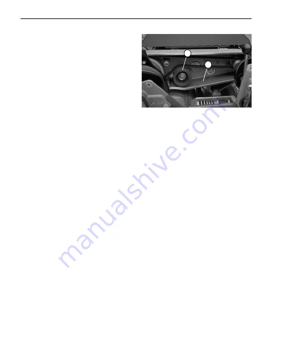
Reinstall idler pulley to the countershaft housing

(Fig. 39). Secure idler pulley with cap screw and lock
washer. Tighten cap screw until washer just starts to
compress. Spacer must be free to rotate (Fig. 37).

3.

Adjust differential belt tension and reinstall front and

rear box covers (see Differential Belt Adjustment).

1. Idler 

pulley

2. Countershaft 

housing

Figure 39

1

2

Summary of Contents for Greenmaster 1000

Page 1: ...e Model and Serial Num ber to The Toro Company 8111 Lyndale Avenue South Minneapolis MN 55420 1196 The Toro Company reserves the right to change product specifications or this publication without noti...

Page 2: ...Greensmaster 1000 1600...

Page 3: ...4 8 Chapter 5 Electrical System Wiring Schematics 5 2 Special Tools 5 6 Trouble Shooting 5 7 Component Testing 5 8 Service and Repairs 5 13 Chapter 6 Controls Wheels and Accessories Specifications 6...

Page 4: ...Greensmaster 1000 1600...

Page 5: ...Lyndale Avenue South Minneapolis Minnesota 55420 1196 2 Never allow children to operate the machine nor al low adults to operate it without proper instructions 3 Become familiar with the controls and...

Page 6: ...enough to cause burns 18 If the cutting unit strikes a solid object or vibrates ab normally stop immediately turn engine off wait for all motion to stop and inspect for damage A damaged reel or bedkni...

Page 7: ...ents from your Authorized Toro Distributor On Control Panel Part No 93 6085 On Control Panel Part No 93 6084 On Belt Cover Part No 65 7660 On Grass Shield Part No 62 5070 On Fuel Tank Part No 88 7620...

Page 8: ...Greensmaster 1000 1600 Page 1 4 Safety On Control Panel Part No 93 9012...

Page 9: ...FICATIONS 3 Capscrew Markings and Torque Values U S 3 Capscrew Markings and Torque Values Metric 3 OPERATION AND SERVICE HISTORY REPORT 5 Product Records Record information about your Greensmaster 100...

Page 10: ...Greensmaster 1000 1600 Page 2 2 Product Records and Manuals Equivalents and Conversions...

Page 11: ...Product Records and Manuals Greensmaster 1000 1600 Page 2 3 Product Records and Manuals Torque Specifications...

Page 12: ...Greensmaster 1000 1600 Page 2 4 Product Records and Manuals...

Page 13: ...te Purchased ____________________ Warranty Expires__________ Purchased From ____________________ ____________________ ____________________ Contacts Parts ____________________ Phone__________________ S...

Page 14: ...n Drive Belts B Level Service Change Engine Oil 1 Clean Combustion Chamber 1 Replace Spark Plug Check Cut Off Bar Adjustment C Level Service Service Air Cleaner Filter 2 Clean Combustion Chamber 2 Rep...

Page 15: ...S Safety Interlock Operation Park Brake Operation Fuel Level Engine Oil Level Air Filter Pre Cleaner Clean Engine Cooling Fins Unusual Engine Noises Unusual Operating Noises Reel to Bedknife Adjustmen...

Page 16: ..._____________________________ _______________________________ _______________________________ D Service every 200 hours Other Annual Service and Specials Additional Servicing Items Clean Combustion Ch...

Page 17: ...Fuel Shut off Valve 5 ADJUSTMENTS 6 Throttle Linkage Adjustment 6 Clutch Control Adjustment 6 Adjusting V belts 7 SERVICE AND REPAIRS 8 Engine Oil 8 Spark Plug and Ignition Components 8 Air Cleaner 9...

Page 18: ...al tools are described in the Kawasaki FE161 FE170 Service Manual and Kawasaki FE120 Service Manual Supplement The use of some specialized test equip ment is explained However the cost of the test equ...

Page 19: ...l flyweight Idle Speed no load 1600 100 RPM at crankshaft or 800 50 RPM at camshaft High Idle no load 3600 100 RPM at crankshaft or 1800 50 RPM at camshaft Direction of rotation Clockwise facing PTO s...

Page 20: ...anol gasoline containing more than 10 ethanol gasoline additives premium gasoline or white gas Engine fuel system damage could re sult 1 Park mower on a level surface Make sure engine is OFF 2 Clean a...

Page 21: ...lve The valve is located on the left front side of the engine It has two positions CLOSED and OPEN Position valve to the closed position when storing or transporting the machine Open valve before star...

Page 22: ...d just high speed idle screw in or out to attain the cor rect speed setting Figure 2 1 Throttle cable screw 2 Throttle cable 3 Governor lever 4 Low speed idle screw 5 High speed idle screw 1 3 2 5 4 5...

Page 23: ...NSION BELTS Tighten cap screws 4 Check that a force of 7 to 9 lbs 31 to 40 N is re quired to engage the clutch control Adjust engine in slots as necessary to get required tension on V belts 5 After te...

Page 24: ...low add only enough oil see chart below for proper viscosity to raise the level to the filler opening Use any high quality detergent oil having the American Petroleum Institute API service classificat...

Page 25: ...not twist element because foam may tear B DRY by wrapping the element in a clean rag Squeeze rag and foam element to dry C SATURATE element with clean engine oil Squeeze element to remove excess oil...

Page 26: ...Lock nut 27 Washer 28 Clutch torsion spring 29 Belt shield 30 Cap screw 31 Clutch lever 32 Cable link assembly 33 Lock washer 34 V belt matched set 35 Washer 36 Cap screw 37 Lock nut 38 Pulley support...

Page 27: ...f the nut Fig 14 B Remove cap screw 23 flat washers 7 and lock nut 26 from the engine base 49 and throttle cable bracket 24 Pull throttle cable 47 and bracket clear of the engine Fig 12 5 Remove engin...

Page 28: ...w and hand tighten C Use scribe mark on engine block to align engine The distance between engine out put shaft center and and power shaft center should be from 5 11 to 5 23 inches 130 to 133 mm Inside...

Page 29: ...is recommended for best results 1 Park mower on a level surface Make sure engine is OFF Remove high tension lead from the spark plug 2 Wipe each grease fitting with a clean rag IMPORTANT Do not apply...

Page 30: ...Greensmaster 1000 1600 Page 3 14 Engine...

Page 31: ...r Pulley and Bearing 9 Clutch Bearing 10 Drum Drive Assembly 12 Drum Drive Belt Replacement 13 Drum Drive Idler Pulley and Bearing 13 Differential Axle Pulley and Bearing 14 Drum Shaft Bearing 15 Drum...

Page 32: ...rive Engine to countershaft drive has two A section V belts Countershaft to differential drive has 5 mm pitch timing belt Differential to drum drive has a 8 mm pitch timing belt Differential Peerless...

Page 33: ...plier Drum Bushing Tool Kit TOR4060 Note This kit is used on mowers with drums that have bushings instead of bearings The kit is used for models 04051 and 04052 50101 to 59999 only This kit contains a...

Page 34: ...n idler pulley cap screw on the engine side of the housing Fig 3 C Pivot idler pulley clockwise against the backside of the belt until desired belt tension is attained Do not over tension the belt Fig...

Page 35: ...ey clockwise against the back side of the belt until desired belt tension is attained Do not over tension belt Fig 6 E Tighten cap screw to lock adjustment Fig 5 Note Make sure spacer is on the lower...

Page 36: ...idler pulley cap screw Fig 8 D Pivot the idler pulley clockwise against the back side of the belt until desired belt tension is attained Do not over tension belt Fig 9 E Tighten cap screw to lock adju...

Page 37: ...10 is shown with the bellcrank cover re moved for illustrative purposes It is not necessary to re move the cover 3 Loosen retainer securing the bellcrank cover Pivot cover open 4 To increase cable te...

Page 38: ...screw 28 Clutch boot 29 Knob 30 Groomer arm cover 31 Cover trim 32 Flat head screw 33 Nut 34 Bearing housing 35 Seal 36 Cover standoff 37 Self aligning bearing 38 Retaining ring 39 Seal 40 Wave washer...

Page 39: ...Drive Idler Pulley and Bearing Removal 1 Remove reel drive belt from the reel drive assembly see Reel Drive Belt Replacement Removal 2 Remove cap screw 2 and lock washer 47 from the pulley support spa...

Page 40: ...ing 8 from clutch housing 1 2 Pull ball bearing 4 from the clutch housing 1 Re move wave washer 7 replace if damaged or worn 3 Remove oil seal 6 from clutch housing 1 Clutch Housing Assembly Fig 11 1...

Page 41: ...cing the clutch jaw driver Secure assembly to the shaft with the lock washer and jam nut Fig 14 8 Place end of clutch lever 24 with actuator pin 19 through the clutch housing 1 Seat clutch boot 28 in...

Page 42: ...Bearing 22 Flangette 23 Grease fitting 24 Bearing lock nut 25 Seal 26 Bearing 27 Bearing housing 28 Closure 29 Bearing clamp 30 Seal 31 Lock nut 32 Cap screw 33 Drum belt cover LH Drum belt cover RH...

Page 43: ...4 Replace both wheels if they were attached see Wheels in the Service and Repairs section of Chapter 6 Wheels and Accessories 1 Idler pulley 2 Drum drive belt Figure 18 2 1 Drum Drive Idler Pulley and...

Page 44: ...he grease fitting side of the housing Installation Fig 19 1 Park mower on a level surface Make sure engine is OFF Remove high tension lead from the spark plug 2 Slide housing over the differential axl...

Page 45: ...2 Install bearing to the drum shaft and frame as fol lows Fig 23 A Place bearing between flangettes with the collar on the bearing towards the flangette without the grease fitting B Insert two cap scr...

Page 46: ...e drums Remove spindle and hub assembly from both drums 3 Remove lock nut and seal spacer from the drum spindle Carefully slide drum spindle out of the drum hub bearings 4 Remove both spring lip seals...

Page 47: ...four cap screws and lock washers Tighten screws using an alternating pattern Repeat tightening sequence a second time 5 Secure drum spindle to the drum with four cap screws and lock washers Tighten sc...

Page 48: ...ve drum shaft from the drum Fig 26 3 Remove bushings from the drum Fig 27 A Insert bushing driver against the bushing B Drive bushing out of the drum by striking the end of the bushing driver with a h...

Page 49: ...e bushing with reamer being careful to keep the reamer square with the drum race C Clean inside bushing so it is free of debris 7 Install oil seal into drum Fig 32 and 28 A Install adapter sleeve on t...

Page 50: ...ting 29 Seal 30 Bearing 31 Long Spacer 32 Countershaft pulley 33 Key 34 Countershaft seal 35 Belt 36 Cap screw 37 Front box cover 38 Rear box cover 39 Cap screw 40 Lock washer 41 Hose clamp 42 Hose cl...

Page 51: ...3 Attach new brake band to the counter shaft housing as follows Fig 35 Note Make sure both cotter pins are locked so there is no contact between the input shaft pulley and cotter pins A Secure lower e...

Page 52: ...g 36 1 Press new seal with its flat side up through the flange side of the bearing housing 2 Press new bearing into the flange side of the bear ing housing 3 Press second new seal with its flat side u...

Page 53: ...s original position to prevent possible dam age to the remaining differential axle bearing 7 Slide flangettes 6 and 8 and bearing 9 of the dif ferential axle Fig 33 Installation 1 Park mower on a leve...

Page 54: ...ng ring 48 from the pulley 44 2 Press spacer 54 out of the pulley 44 Press bear ings 45 out of the pulley Assembly Fig 33 1 Press bearings 45 into the pulley 44 Press spacer 54 into the pulley 2 Insta...

Page 55: ...he left differential axle see Differential Axle Pulley and Bearing Removal IMPORTANT For the remainder of this procedure support the axle in its original position to prevent possible damage to the dif...

Page 56: ...emove washer 4 Remove both retaining rings from each axle Sepa rate the bevel gears from each axle Note The differential carrier housings come as sembled with both bearings and oil seal It may be more...

Page 57: ...e the teeth of the bevel and pinion gears mesh Fig 45 8 Secure both differential carrier housings together as follows Fig 45 A Position the open ends of each housing together so the teeth of both beve...

Page 58: ...ial axle see Differential Axle Pulley and Bearing Installa tion IMPORTANT Align axles so they turn freely before striking the locking collar 9 Lock locking collar by striking it with a punch in the co...

Page 59: ...ing to side plate Rotate housing 180 so the bottom of the housing points upward Fig 46 and 48 7 Remove both cap screws and lock nuts securing the clutch housing to the side plate Rotate housing 180 so...

Page 60: ...e This will keep the engine in place C Remove four capscrews lock washers and flat washers securing the countershaft housing to the frame 4 Remove idler pulley from the bellcrank assembly Remove remai...

Page 61: ...to the frame B Remove upper carriage bolts and lock nuts se curing the idler brackets to the frame C Swing both idler pulleys forward Remove belts 9 Remove shaft input pulley from the power shaft Re...

Page 62: ...ng off the power shaft Alternate the hammer between the long axle and the bearing housing end of the counter shaft housing to prevent damage to the bearings Fig 60 14 Remove three socket head cap scre...

Page 63: ...sing with the small hose clamp 7 Make sure drum belts will be properly aligned A Center both pulleys on the differential axles to obtain an equal distance between the side plates and pulleys Fig 63 B...

Page 64: ...gs and increase wear on the belt 12 Adjust tensions of differential and both drum drive belts from 20 to 25 lbs 89 to 111 N of force Use a scale to pull on the idler pulley while securing the idler br...

Page 65: ...ngine is OFF Remove high tension lead from the spark plug 2 Wipe each grease fitting with a clean rag IMPORTANT Do not apply too much pressure or grease seals will become permanently damaged 3 The gre...

Page 66: ...Greensmaster 1000 1600 Traction and Reel Drive Systems Page 4 36...

Page 67: ...rly Model Kawasaki FE120 Engines With Operator Presence Control 5 SPECIAL TOOLS 6 TROUBLESHOOTING 7 Engine Will Not Start 7 Engine Will Start But Will Not Run 7 COMPONENT TESTING 8 Interlock Module an...

Page 68: ...ACK BLACK Late Model Kawasaki FE120 Engines ON OFF switch is open in the ON position CLUTCH SWITCH is closed when the clutch is DISENGAGED HIGH TENSION LEAD FLYWHEEL RED Note There are two types of ig...

Page 69: ...CLUTCH SWITCH is closed when the clutch is DISENGAGED HIGH TENSION LEAD FLYWHEEL with Operator Presence Control BROWN BLACK WHITE BLACK WHITE BROWN SWITCH OPERATOR OPERATOR PRESENCE SWITCH is closed...

Page 70: ...arly Model Kawasaki FE120 Engines ON OFF switch is open in the ON position CLUTCH SWITCH is closed when the clutch is DISENGAGED HIGH TENSION LEAD FLYWHEEL RED IGNITOR Note There are two types of igni...

Page 71: ...N BROWN CLUTCH PRESENCE SWITCH CONNECTOR INTERLOCK MODULE BLACK WHITE BLACK WHITE BROWN BLACK WHITE BLACK WHITE BROWN SWITCH OPERATOR RED with Operator Presence Control OPERATOR PRESENCE SWITCH is clo...

Page 72: ...uits The high impedance internal resistance of a digital me ter in the voltage mode will make sure that excess cur rent is not allowed through the meter This excess current can cause damage to circuit...

Page 73: ...ystem How ever ignition system testing is covered in this chapter The ignition system for the FE120 engine is not fully cov ered in the service manual Problem Possible Causes Correction Engine will no...

Page 74: ...nd the engine Check all other electrical connections and the interlock module for damage Re place any damaged wiring or components 2 Check the adjustment and continuity of the clutch switch A Disconne...

Page 75: ...itch from both brown wires leading from the wire har ness B Hold the bail against the handle The switch should be closed C Release the bail from the handle The switch should be open D Adjust operator...

Page 76: ...he engine The spark plug is necessary to maintain normal starting speeds 1 Remove high tension lead from the spark plug and connect it to the test spark plug 2 Connect large spring clip around the hex...

Page 77: ...e bottom of the igniter 3 Use a digital multimeter set to the ohms scale take internal resistance of the igniter A Contact black test lead to the igniter mount ing screw ground B Contact red test lead...

Page 78: ...e is OFF 2 Isolate ignition coil Disconnect high tension lead from spark plug and black wire on the coil 3 Measure primary winding resistance between the primary lead and ground Winding resistance sho...

Page 79: ...traction lever and verify that the switch plunger is depressed no more than 0 06inch 1 5 mm switch open Readjust as required Removal A Disconnect black white wires at the switch from the brown wires...

Page 80: ...more than 0 06inch 1 5 mm switch open Readjust as required Removal A Disconnect black white wires at the switch from the brown wires leading from the wire harness B Remove adjusting nut from the plun...

Page 81: ...plug can give an ac curate picture of the overall condition of the engine Use the chart on the following page as a guide to determine possible problems with the engine 3 Inspect the spark plug IMPORT...

Page 82: ...he bore Excessive oil entering the combustion chamber through excessive clearances be tween valve guides and stems worn or loose bearings or worn rings and pistons Replace spark plug Has gray or light...

Page 83: ...ols Wheels and Accessories Table of Contents SPECIFICATIONS 2 ADJUSTMENTS 3 Handle Height Adjustment 3 SERVICE AND REPAIRS 4 Handle Assembly 4 Brake Cable Replacement 6 Clutch Cable Replacement 7 Thro...

Page 84: ...Greensmaster 1000 1600 Page 6 2 Wheels and Accessories Specifications Item Description Tire pressure 12 to 15 PSI 0 83 to 1 04 bar Wheel Shaft torque 65 to 75 ft lb 8 99 to 10 37 kg m...

Page 85: ...a level surface with the engine OFF 2 Remove cotter pins from the ring pins on each side of the mower 3 Support handle and remove ring pins from each side of the mower Raise or lower handle to the de...

Page 86: ...ring lock washer 23 Flat washer 24 Spacer 25 Clutch lever 26 Lock nut 27 Clutch bracket 28 Black knob 29 Console 30 Cap screw 31 Spring lock washer 32 Flat washer 33 Handle pivot pin 34 Lock insert nu...

Page 87: ...to be removed from the handle arms to allow handle installation Fig 4 1 Slide handle ends through the holes in the handle arms Squeeze handle ends inward Install handle ends to the handle pivot pins 3...

Page 88: ...s and switch bracket with switch at tached from the brake skid bracket Remove shoul der bolt and spacer from the bail assembly and brake skid bracket Remove console bracket from the brake skid bracket...

Page 89: ...Run new brake cable to the countershaft assembly Install new brake cable to the countershaft housing and brake lever as follows Fig 5 A Attach brake cable to the counter shaft housing and tighten the...

Page 90: ...as follows Fig 8 A If the operator presence kit is installed remove both screws from clutch skid bracket Remove shoulder bolt and spacer from the bail assembly and clutch skid bracket Remove console b...

Page 91: ...four screws 13 Fig 2 5 Run new clutch cable to the bellcrank assembly Install new cable to the clutch lever as follows Fig 7 A Attach clutch cable to the clutch bracket Tighten nut to secure cable to...

Page 92: ...cket from the clutch skid bracket 7 Snap throttle cable 1 out of the clutch skid bracket 8 Disconnect throttle cable from the throttle lever 6 Fig 2 8 Remove clutch cable from the mower Installation 1...

Page 93: ...wheel shaft has left hand threads 3 If the wheel shafts were removed from the drive pul leys A Apply Loctite 242 or equivalent to the threads of the wheel shafts IMPORTANT The right hand wheel shaft h...

Page 94: ...four cap screws 12 and flange nuts 13 from the deep rim 10 and shallow rim 3 Remove shallow rim from the deep rim 3 Remove bolt 9 from the hub 5 Remove bolt 8 spring 7 and retaining lever 6 from the h...

Page 95: ...m the spring retainer Fig 15 4 Remove both lock nuts 10 flat washers 9 cap screws 1 and spacers 11 from the kickstand 8 and frame Remove kickstand from the frame Fig 14 Installation 1 Make sure mower...

Page 96: ...Greensmaster 1000 1600 Page 6 14 Wheels and Accessories...

Page 97: ...HOOTING 7 Factors Affecting Quality of Cut 7 ADJUSTMENTS 9 Leveling Drum to Reel 9 Bedknife to Reel Adjustment 10 Height of Cut Adjustment 11 Grass Shield Height Adjustment 12 Cutoff Bar Adjustment 12...

Page 98: ...ction of the GR1000 The cutting unit consists of the frame assem bly reel assembly drum assembly and detachable bas ket The reel and drum drive assemblies make up part of the cutting unit and their co...

Page 99: ...0 21 inches 53 3 cm CLIP GR1000 0 16 inch 0 41 cm REEL CONSTRUCTION GR1600 5 inch 12 7 cm diameter 8 carbon steel blades welded to 6 stamped steel spiders HEIGHT OF CUT RANGE GR100 1 8 to 1 1 4 inch 3...

Page 100: ...smaster 1000 1600 Page 7 4 Cutting Unit General Information Grass Basket Installation 1 Grasp basket by top rear lip and slide on or off the basket mounting rods Figure 2 1 1 Grass basket 2 Mounting r...

Page 101: ...Bar Assembly P N 13 8199 Used to verify height of cut Figure 3 Backlapping Brush Assembly TOR299100 Used to apply lapping compound to cutting units while keeping the operator s hands at a safe distan...

Page 102: ...Bearing Replacement Tool Kit TOR238900A The puller is used to remove the bearings from the roll ers A driving tube is used to install bearings into the roll er A drill bushing is used to drill into be...

Page 103: ...nd bedknife sharpness A reel and or bedknife that has rounded cutting edges or rifling grooved or wavy appearance cannot be corrected by tightening the bedknife to reel contact Grind reel to remove ta...

Page 104: ...s are securely seated Check condition of the bushings in the side plates See Bedbar in Service and Repairs section Number of reel blades Use correct number of blades for clip frequency and optimum hei...

Page 105: ...sing down on reel slide a feeler gauge under one end of the drum then check the other end of the drum If there is a gap between the drum and the work surface greater than 0 010 inch 0 254 mm on ei the...

Page 106: ...r is pinched lightly C On the GR1600 while slowly rotating the reel forward tighten bedbar adjusting screw clockwise one click at a time until the paper is pinched lightly D When inserted from the fro...

Page 107: ...l the roller contacts the front of the gauge bar Adjust both ends of the roller until the entire roller is parallel to the bedknife Fig 13 IMPORTANT When set properly the roller and drum should contac...

Page 108: ...The bar should be adjusted closer to the reel for extremely wet turf However adjust cutoff bar further away from the reel for dry turf The bar should be parallel to the reel to assure optimum perfor...

Page 109: ...Form No 80 300 PT 1 Cover plug Figure 19 1 Lubrication The grease fittings on the mower should be greased at least every 25 hours Grease immediately after wash ing regardless of the service interval...

Page 110: ...release suddenly WARNING 3 Compress spring with a pair of channel lock pliers Insert a pin to hold the spring in position Fig 22 4 Loosen flange nuts on both sides of the mower Re move both bedbar bo...

Page 111: ...s of the frame Fig 27 Use caution when removing the bedbar Ad justing screw springs are under tension and could release suddenly Fig 28 WARNING 5 Compress spring with channel lock pliers Remove pin fr...

Page 112: ...end of the bedknife Fig 32 Grinding Since there can be variations in the mounting surface of the bedbar a new bedknife will not be perfectly flat after it is installed Because of this it is necessary...

Page 113: ...t screw and then the jam nut 4 Adjustroller for height of cut see Height of Cut in the Adjustments section Roller Bearing Replacement Note A Wiehle roller is shown Bearing configura tions is the same...

Page 114: ...remove both flat head screws groomer arm cover and both cover standoffs from the bearing housing Fig 36 8 Remove both cap screws lock nuts and bearing cover from the bearing housing LH Fig 37 9 Remove...

Page 115: ...g 36 A Push housing onto reel shaft If necessary tap into position with a soft hammer B Make sure grease fitting hole is position to the front of the mower C Attach the groomer arm cover to the bearin...

Page 116: ...ll result in the the reel being ground to the desired cylinder shape Note When grinding be careful to not overheat the reel blades Remove small amounts of material with each pass of the grinder 4 Afte...

Page 117: ...4 Grooming Reel Mechanical Problems 5 ADJUSTMENTS 6 Height Depth of Grooming Adjustment 6 Drive Belt Tension Adjustment 7 Note This chapter covers the grooming reel kit Mod el No 04125 which is used o...

Page 118: ...stable at 1 4 and 3 4 inch 6 4 and 19 1 mm by varying the number of blades and spacers GROOMING PENETRATION Maximum of 0 18 inch 4 6 mm MICRO ADJUSTMENT KNOB Allows a 0 007 inch 0 18 mm increment of h...

Page 119: ...er and engage the clutch by turning the clutch knob counterclockwise 2 Turn clutch knob clockwise to disengage the clutch Transport Mode IMPORTANT When transporting the mower make sure groomer clutch...

Page 120: ...Use the groomer carefully READ AND UNDERSTAND THE OPERA TOR S BEFORE OPERATING OR TESTING GROOM ER PERFORMANCE Variables That Affect the Use and Performance of Grooming Reels 1 The Growing season and...

Page 121: ...e clutch knob set screws are tight against the flats on the re lease disk and do not allow clutch knob to slip IMPORTANT When engaging or disengaging the clutch be sure to push the snubber down and tu...

Page 122: ...bber down and disengage the clutch by turning the clutch knob clockwise Use quick up le vers on both sides of the mower to lower the grooming reel into the grooming position Fig 2 4 On one end of the...

Page 123: ...ulley B Drive belt deflection should be about 0 25 inch 6 4 mm C If belt tension is not acceptable loosen the sock et head cap screw on the idler block D Pivot idler to get proper tension on the drive...

Page 124: ...5 Driver 16 Spring 17 Adjustment knob 18 Pin cover 19 Roll pin 20 Cap 21 Ramp 22 Mounting block 23 Spring 24 Pop rivet 25 Caution plate 26 Spring 27 Lock nut 28 Spring spacer 29 Clutch assembly 30 Fla...

Page 125: ...t screws in the clutch knob Remove clutch knob and poly washer from the clutch assembly Fig 6 3 Remove three socket head cap screws and wash ers then remove belt cover Fig 7 4 In the belt drive housin...

Page 126: ...Make sure engine is OFF Remove high tension lead from the spark plug 2 Place grooming reel shaft 53 into the belt drive housing 46 Screw driven pulley 41 on the shaft Do not tighten Fig 5 3 From the r...

Page 127: ...ring Figure 12 1 3 4 2 1 Outer ball bearing 2 Bearing housing 3 Driven pulley spacer 4 Inner ball bearing Figure 13 1 4 3 2 Drive Belt Replacement 1 Park mower on a level surface Make sure engine is O...

Page 128: ...e special screw clutch pin and compression spring from the driver pulley 2 Separate flange bushing clutch release disc and both belleville washers from the driver pulley 3 Inspect needle and roller be...

Page 129: ...on the driver pulley and slide clutch onto the clutch adapter shaft while sliding the belt onto the driven pulley Fig 14 5 Secure flat washer to the clutch adapter shaft with the lock nut Torque lock...

Page 130: ...15 Driver 16 Spring 17 Adjustment knob 18 Pin cover 19 Roll pin 20 Cap 21 Ramp 22 Mounting block 23 Spring 24 Pop rivet 25 Caution plate 26 Spring 27 Lock nut 28 Spring spacer 29 Clutch assembly 30 F...

Page 131: ...d 1 Make sure engine is OFF Remove high tension lead from the spark plug Place mower on a level surface or on a workbench 2 Remove four cap crews and lock washers and then the reel drive cover Fig 19...

Page 132: ...crews on the clutch knob Remove the clutch knob and the poly washer behind it from the clutch assembly Fig 18 9 Remove the three socket head cap screws 33 and lock washers 32 Remove belt cover 31 from...

Page 133: ...ing Slide adapter through the bearing then slide the screws through the slots in the housing E Insert a slot cover onto each flat head socket screw while aligning the curved side of the cover with the...

Page 134: ...mplete the reinstallation of the clutch assembly and belt drive housing by following the instructions in Clutch Assembly Reinstallation Fig 30 11 Use a 1 2 inch drive ratchet and extension to rein sta...

Page 135: ...vers to raise the groom ing reel into the transport position B Hold the clutch snubber down and rotate the clutch knob clockwise to disengage the clutch C Correct any problems and recheck assembly 1 Q...

Page 136: ...ing from the bearing housing LH Fig 33 Installation 1 Make sure engine is OFF Remove high tension lead from the spark plug Place mower on a flat level sur face or on a stable work bench IMPORTANT Make...

Page 137: ...nto the reel shaft Fig 33 A Push housing onto reel shaft If necessary tap into position with a soft hammer B Make sure grease fitting hole is positioned to the front of the mower 7 Secure cutting reel...

Page 138: ...Greensmaster 1000 Grooming Reel Kit Page 8 22...

Page 139: ......

Page 140: ...Commercial Products PART NO 96889SL Rev A The Toro Company 1996 1997 Printed in U S A...

Reviews: