background image

GB–11

repeating engine starting procedure, check
that ignition key switch is ON, and make sure
there is fresh fuel in fuel tank.  If engine still
will not start after a second attempt, bring the
snowthrower to an Authorized Toro Service
Dealer for servicing.

IMPORTANT: Do not leave the electric
starter cord connected to the power outlet
when storing the snowthrower.  It should only
be connected to the power outlet during the
starting procedure.  If you leave it connected
to the power outlet during storage, a power
surge could start the snowthrower when no
one is in attendance.

5.

When engine starts, move choke lever to middle
position after a few seconds of running time.
After engine has warmed up, move choke lever
to OFF (far left) position.

6.

TO START/STOP ROTOR—To start the rotor,
squeeze the control bar to the handle.  When the
control bar handle is released, the rotor blades
stop, but the engine continues to run.

7.

TO STOP ENGINE—Release the control bar to
stop the rotor, turn key to OFF, and wait for all
moving parts to stop before leaving operator’s
position.

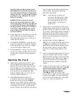
Operating Tips (Fig. 8)

1.

ADJUSTING DISCHARGE CHUTE—Move
the chute handle left and right to adjust the
direction of the snow stream.  Rotate the chute
deflector handle on top of the discharge chute
forward and backward to adjust the height of the
snow stream. Do not overtighten the chute
deflector mounting nuts so excessive force is
required to adjust the deflector.

2.

SELF–PROPELLING ACTION—The
snowthrower clears down to the ground and
propels itself forward when tilted slightly
forward so rotor blades strike the ground. The
wheels do not have to touch the ground in order
to self-propel. The further you tilt the handle
forward, the faster the snowthrower self-propels.

However, depth of snow affects forward speed.
Always overlap each swath and discharge
downwind when possible.

Note:

If snowthrower is tilted too far
forward, it will self-propel at a rapid
rate and snow will spray back at the
feet of the operator. Reduce lift on
handle slightly to self-propel at a
moderate rate.

3.

Keep the area to be cleared free of stones, toys,
or other foreign objects which may be picked up
and thrown by the rotor blades. Such items could
be covered by snowfall and, therefore, unnoticed
until struck by the rotor blades. Always be sure
to keep all people and pets away from area of
operation to prevent possibility of being hit by
thrown objects.

4.

ON STEPS OR CUTTING THROUGH
DRIFTS—It is recommended that operator stand
on right side of snowthrower and hold it by
upper handle and chute handle (standing on left
side may expose operator to engine exhaust).
Use a side–to–side sweeping motion to clear
snow.

5.

It is not recommended that snowthrower be used
on gravel or crushed rock driveways or walks.
Should you find it necessary to clear snow from
crushed rock or gravel, push down on handle to
raise rotor blades clear of loose material that
could be thrown by the blades and push unit
forward.

6.

In some snow and cold weather conditions, some
controls and moving parts may freeze solid. DO
NOT USE EXCESSIVE FORCE WHEN
TRYING TO OPERATE FROZEN
CONTROLS. 
When any control or part
becomes hard to operate, start the engine and let
it run for a few minutes. If control or part still
will not move with moderate force, stop engine,
remove ice or thaw out snowthrower.

Summary of Contents for CCR POWERLITE 38177

Page 1: ...Operator s Manual FORM NO 3321 772 CCR POWERLITE Snowthrower Model No 38177 9900001 Up Model No 38178 9900001 Up ...

Page 2: ...21 1 Model and serial number decal m 3371 1 3 4 5 5 2 4 1 Discharge chute 2 Chute handle 3 Hex bolt 4 Washer 5 Locknut m 4022 4 5 1 3 2 1 Lower handle 2 Upper handle 3 Oval head bolt 4 Knob 5 Curved washers 897 4 3 2 1 1 Spring 2 Cable adjuster 3 Cable 4 Z fitting 1 2 3 4 ...

Page 3: ...2 3 1 Add oil to small amount of gasoline 2 Install cap and shake can to mix 3 Add remaining amount of gasoline m 3992 1 2 3 5 6 4 1 Key switch 2 Primer 3 Recoil start 4 Choke lever 5 Elec start button 6 Cord connection ELEC START MODEL m 3370 3 1 2 1 Chute handle 2 Chute deflector handle 3 Deflector mounting nuts 5 6 7 8 ...

Page 4: ...arge chute 2 Discharge chute handle 3 Handle 921 1 1 Wear indicator hole 929 8 2 7 4 4 1 1 1 1 3 6 5 1 Torx screw 2 Capscrew 3 Locknut 4 Blade support 5 Drive belt cover 6 Thick layer 7 Thin layer 8 Wear indicator hole 9 10 11 ...

Page 5: ...2 Wear indicator groove 924 1 2 1 Scraper 2 Screws 925 1 2 1 1 Self tapping screws 2 Capscrew nut washer m 4014 3 4 1 2 5 6 1 Rotor pulley 2 Drive pulley 3 Idler pulley 4 Drive belt 5 Brake arm 6 Idler pivot nut 12 13 14 15 ...

Page 6: ... m 4015 1 3 4 2 5 6 1 Idler pulley 2 Engine mounting nuts 3 of 4 shown 3 Idler spring 4 Hole 5 Brake arm 6 Belt guide 917 2 1 1 Control panel 2 Screws 918 1 1 Spark plug wire 110 0 030 76 mm 16 17 18 19 ...

Page 7: ...t information about your specific product You will find the model and serial number decal located in a unique place on the product as shown in Figure 1 For your convenience write the product model and serial numbers in the space below Model No Serial No Read this manual carefully to learn how to operate and maintain your product correctly Reading this manual will help you and others avoid personal...

Page 8: ...wer only after reading this manual 3 Keep everyone especially children and pets away from the snowthrower and area of operation 4 Inspect area thoroughly where snowthrower will be used Remove doormats sleds boards sticks wire and any other foreign objects which might be picked up and thrown by the snowthrower 5 Keep all shields and safety devices in place If a shield safety device or decal is ille...

Page 9: ... operating procedure 22 If a foreign object is hit or snowthrower vibrates abnormally stop engine by turning key to OFF disconnect spark plug wire disconnect the cord on electric start units and wait for all moving parts to stop Check snowthrower immediately for possible damage an obstruction or loose parts Vibration is generally a sign of trouble Repair any damage before operating snowthrower aga...

Page 10: ...heck all fasteners frequently to ensure they are tight 35 To ensure optimum performance and safety purchase genuine TORO replacement parts and accessories to keep your TORO all TORO NEVER USE WILL FIT REPLACEMENT PARTS AND ACCESSORIES Sound Pressure Level This unit has a sound pressure at the operator s ear of 90 dBA based on measurements of identical machines per Directive 81 1051 EEC Sound Power...

Page 11: ...nd remove key before leaving operator position single stage snowthrower Electrical shock electrocution Shut off engine and remove key before leaving operator position two stage snowthrower Cutting or entanglement of foot rotating auger Severing of fingers or hand impeller blade Electric start Hot surfaces burns to fingers or hands Machine loss of control uphill slope Caustic liquids chemical burns...

Page 12: ...not tip battery Traction drive Keep dry Snowthrower collector auger Machine travel direction forward Engage Machine travel direction rearward Disengage On start Choke Off stop Engine speed Throttle Fast Neutral ...

Page 13: ...auger Decreasing Increasing Lock Engine start Unlock Engine stop Lever operation Snowthrower chute direction Lever operation Primer start aid Unleaded fuel Primer operation Cutting of fingers or hand Throttle operation Cutting of foot ...

Page 14: ...trol bar is on the upper side of the handle 2 Secure upper handle to lower handles using oval head bolts curved washers and knobs Position knobs and curved washers on inside of handle and TIGHTEN KNOBS SECURELY to prevent them from loosening Note Make sure the oval head bolts and curved washers are aligned correctly as shown in Figure 3 to prevent knobs from loosening Install Control Cable 1 Route...

Page 15: ...lug life Use of premium grade fuel is not necessary 1 APPROVED OIL For simplicity and best engine performance mix the contents of one 5 2 ounce bottle of Toro 50 1 Two Cycle Oil with two gallons of fresh unleaded regular gasoline You can also use Toro Easy Mix Two Cycle Oil 3 2 ounce bottle mixed one per gallon of gasoline 40 1 ratio in this Toro two cycle engine Leaded regular gasoline may be use...

Page 16: ...orner of the control panel 2 Turn key to ON and move choke lever to ON far right position 3 Cover hole in center of primer with thumb and push primer twice slowly 1 to 2 seconds per prime for temperatures above 0_F 18_C Push primer slowly three times for temperatures below 0_F 18_C DO NOT PRIME IF THE ENGINE HAS BEEN RUNNING AND IS HOT Note When starting engine for first time or after running out ...

Page 17: ...rotor blades strike the ground The wheels do not have to touch the ground in order to self propel The further you tilt the handle forward the faster the snowthrower self propels However depth of snow affects forward speed Always overlap each swath and discharge downwind when possible Note If snowthrower is tilted too far forward it will self propel at a rapid rate and snow will spray back at the f...

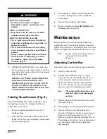
Page 18: ... to prevent losing them 3 Loosen knobs on handle and fold handle down over unit ensuring that you do not kink the control cable 4 Carry unit by discharge chute handle 5 Be sure to tighten all knobs SECURELY after unfolding handle and chute Maintenance Keep snowthrower in safe operating condition by cleaning the unit Check and tighten any loose nuts bolts knobs and screws The scraper drive belt rot...

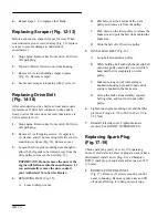
Page 19: ...to be removed from fuel tank Replacing Rotor Blades Fig 10 11 Before each snow season inspect rotor blades for wear When blade edge has worn to the wear indicator hole Fig 10 the blades must be replaced to ensure proper performance and prevent damage to underside of snowthrower Always replace both blades at the same time Note Whenever rotor blades are replaced scraper should also be replaced to en...

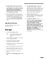
Page 20: ...the nuts contact your Authorized Toro Service Dealer 4 REMOVING BELT Fig 15 A Loosen idler pivot nut B Pull belt out at the bottom of the rotor pulley and remove it from the pulley C Push down on the idler pulley to release the brake arm and pull the belt from behind the brake arm D Slide the belt off of the drive pulley 5 INSTALLING BELT Fig 16 A Loop belt around drive pulley B While holding belt...

Page 21: ... tank or run engine until it stops Restart the engine again and run it until it stops Either choke or prime the engine restart it a third time and run engine until it will not restart Dispose of fuel properly Recycle per local codes DO NOT store STABILIZED gasoline over 90 days 2 CYLINDER PISTON CARE Slowly pull recoil starter until resistance is felt due to compression pressure then stop Release ...

Page 22: ......

Page 23: ......

Page 24: ......

Reviews: