


4
Setup
Note: Determine the left and right sides of the machine
from the normal operating position.
Loose Parts
Note: Use the chart below to identify parts used for assembly.
DESCRIPTION
QTY.
USE
Gage wheel
Shoulder bolt
Locknut, 3/8 in. (with patch on threads)
2
2
2
Install gage wheels
Rear link bracket
Washer, 1/2 in.
Cotter pin, 1 in.
1
2
2
Install rear link bracket
Adjustable links
Washer
Cotter pin, 1 in.
2
2
2
Install front mount to mower
Grass deflector
Spring
Bolt, 3/8 x 3-1/2 in.
Locknut, 3/8 in.
1
2
2
2
Install grass deflector
Up stop
1
Install mower up stop
Hairpin cotter, 3-3/8 in.
Washer, 3/4 in.
Link pin
Hairpin cotter, 2-9/16 in.
Washer
2
2
1
3
3
Install mower to tractor
Operator’s Manual
Warranty card
1
1
Read before operating
Important
If you have a 1999 or earlier tractor and are
installing a 2000 or later 52 in. deck, a kit will be needed to
install the deck. Obtain this kit from an Authorized Service
Dealer.
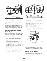
Preparing the Mower
1. Attach gage wheels to the outside of arms on rear
carrier assembly. Grease fitting on wheel must face in
(Fig. 2).
2. Secure with shoulder bolt and lock nut (3/8 in.), with
internal locking patch on threads (Fig. 2).
Summary of Contents for 78281
Page 20: ...20 ...


