background image

Maintenance

WARNING

Disconnect all power sources to the machine before
doing maintenance work.

Note:

Download a free copy of the schematics by visiting

www.Toro.com and searching for your machine from the
Manuals link on the home page.

Lubrication

Lubricating the machine

Use an automotive, all-purpose grease.

Lubricate regularly, after 25 hours of normal operation.

Lubricate daily when operating in extremely dusty and
dirty conditions.

Lubricate all bearings, bushings, and chains.

Lubrication Procedure

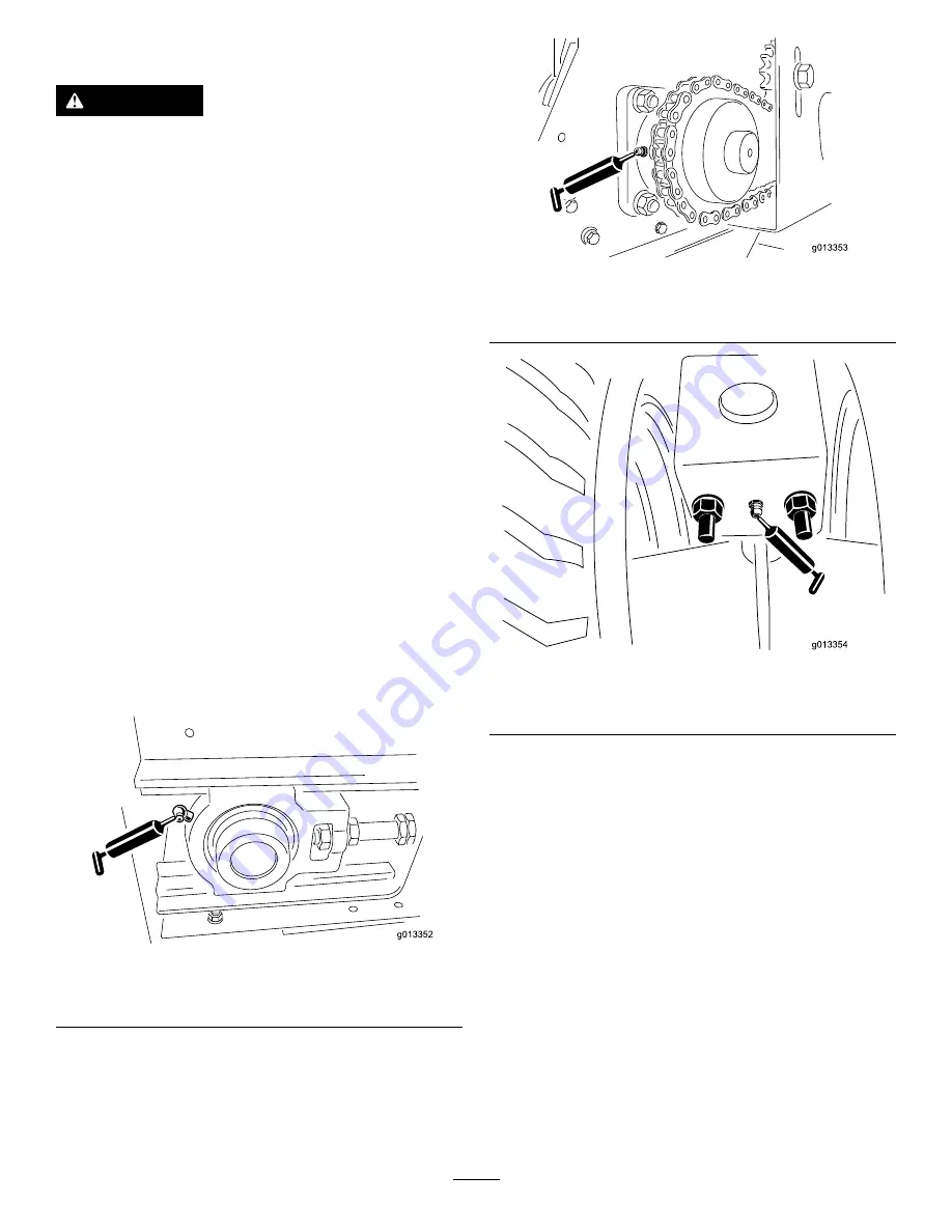
Several grease fittings are located on the machine and the
tow-behind chassis (

Figure 52

,

Figure 53

and

Figure 54

).

1.

Clean the grease fittings.

2.

Pump the grease into the bearings and the bushings.

3.

Clean off the excess grease.

4.

Clean and repack the wheel bearings every year or
every 300 hours of operation

Figure 52

1.

Grease fitting on Base Model (one at left front, one at right
front)

Figure 53

1.

Grease fitting on Base Model (one at left rear, one at right
rear)

Figure 54

1.

Grease fitting on tow-behind chassis (front and rear, left and
right). Grease once per year.

Daily Checks

At the start of each day, complete these safety checks before
operating the machine. Report any safety problems to your
supervisor. See the Safety Instructions in this manual for
details.

Tires and Wheels

The recommended tire pressure for the Tow Chassis is 10
psi (69 kPa), or as recommended by the tire manufacturer.
Refer to the Operator's Manual for the tow vehicle tire
specifications.

Check for excessive wear or visible damage.

Check that the wheel bolts are tight and none are missing.

Rear Gate

Check that the adjustable section of the rear gate opens and
closes without sticking.

34


Summary of Contents for 44701

Page 1: ...Form No 3394 769 Rev A ProPass 200 Top Dresser Model No 44701 Serial No 315000001 and Up Model No 44751 Serial No 315000001 and Up Register at www Toro com Original Instructions EN 3394 769 A...

Page 2: ...oblems This booklet is available from the U S Government Printing Office Washington DC 20402 Stock No 004 000 00345 4 FCC ID OA3MRF24J40MC Base OA3MRF24J40MA Hand Held IC 7693A 24J40MC Base 7693A 24J4...

Page 3: ...to comply with the instruction may result in personal injury or death Safe Operating Practices Training Read the Operator s Manual and other training material carefully Be familiar with the controls s...

Page 4: ...arking brake Stop the engine and remove the key Disengage drive to attachments stop the engine and remove the ignition key before clearing blockages before checking cleaning or working on the machine...

Page 5: ...If possible do not make adjustments with the engine running Charge batteries in an open well ventilated area away from spark and flames Unplug charger before connecting or disconnecting from battery W...

Page 6: ...hat is damaged or lost 119 6809 1 Read the Operator s Manual for instructions on cleaning the machine 119 6808 1 Tailgate height indicator 119 6818 1 Tailgate adjustment 119 6854 1 Floor speed 119 685...

Page 7: ...afe distance from the machine 119 6805 1 Cutting dismemberment hazard impeller stay away from moving parts keep all guards and shields in place 119 6810 1 Read the Operator s Manual 2 Two people requi...

Page 8: ...al 4 Warning stop the engine remove the ignition key and read the Operator s Manual before performing maintenance on the machine 2 Warning do not operate the machine unless you are trained 5 Warning n...

Page 9: ...lange nut 6 Mount the hopper to the tow chassis 5 Intermediate wire harness 1 Connect the intermediate wire harness 6 On Off Pendant 1 Connect the On Off Pendant Model 444701 only Handheld remote 1 AA...

Page 10: ...1 Shipping bracket 3 At the front of the twin spinner remove the 2 bolts and nuts attaching the machine lifting device shipping bracket to the Twin Spinner Figure 4 Figure 4 1 Shipping bracket 4 This...

Page 11: ...tall this harness on the vehicle you plan to use to operate the machine If you will use more than one vehicle with the machine purchase additional power harnesses from your Toro distributor The power...

Page 12: ...power to the positive post on the battery then connect the black wire ground to the negative post on the battery 3 Installing the Hopper Extension Kit Parts needed for this procedure 1 Hopper extensi...

Page 13: ...TDC Chassis connected The lifting bracket is not capable of lifting the entire machine 2 Using a lifting mechanism position the hopper over the tow chassis 3 Line up the 6 mounting holes 3 per side a...

Page 14: ...ure 17 1 On Off pendant 7 Assembling the Handheld Remote Model 44751 Only Parts needed for this procedure 1 Handheld remote 4 AA batteries 1 Magnetic bracket 6 Screws small Procedure 1 Remove the rubb...

Page 15: ...es together to secure the remote and tighten the bolt in the magnet Figure 19 Figure 19 1 Handheld remote 3 Bolt in the magnet 2 Magnetic remote bracket 8 Mounting the Wireless Remote Model 44751 Only...

Page 16: ...the conveyor belt or the option Figure 23 Keep the On Off pendant within reach of the operator Figure 23 1 On off pendant E Stop Button Model 44751 Only When finished working with the machine always...

Page 17: ...5 Option Stop 7 Preset 2 16 Increase Option Speed 8 Preset 3 17 Decrease Option Speed 9 All Stop Stops all functions Specifications Weights Base Model 546 lb 248 kg Twin Spinner 150 lb 68 kg Attachmen...

Page 18: ...lding the jack stand s in place 5 Store the jack stand s as follows On tow behind chassis turn the jack stand 90 degrees counter clockwise until the bottom of the jack stand points to the rear of the...

Page 19: ...y The approximate width is also indicated Checking the Blades Note The machine is shipped with the spinner blades in POSITION B The lighter spreads blue panel remind you to ensure that the spinner bla...

Page 20: ...15 Tailgate Red Slide Adjustment Red Adjusting the Tailgate The tailgate controls the volume of material that flows from the ProPass Figure 33 Figure 33 Tailgate Decal Symbol The 5 inch tailgate is d...

Page 21: ...decal Figure 28 Adjusting the Floor Speed The floor speed for every setting is usually 100 this was developed and tested in order to have one less factor to adjust in the Color Coded Operating System...

Page 22: ...ad the material at a constant speed until the spread reaches the edge of the top dressing area 12 Turn off the conveyor belt turn the machine around and position it for the next pass 13 Before making...

Page 23: ...sts of a handheld remote a 12 to 14 4 VDC Base Unit and a wiring harness Handheld Remote Figure 42 1 LCD display 10 Floor Start 2 Remote status LED 11 Floor Stop 3 All Start Starts Floor and Option 12...

Page 24: ...dheld Remote Press the ON OFF button on the remote and wait for the it to find the base Ensure that there are no buttons being pressed on the hand held while it is performing its start up routine Manu...

Page 25: ...The last saved work settings will be in the current working memory when you turn the handheld remote on Operational sequence of the handheld remote start buttons Pressing a start button once ALL STAR...

Page 26: ...Backlighting consumes the most energy of all Handheld Remote functions Increasing the backlighting increases power consumption and will shorten the life span of the batteries the lower the backlightin...

Page 27: ...hing the LCD screen Associating the Handheld Remote with the Base The factory initially associates the remote to the base allowing them to communicate however there may be instances in the field when...

Page 28: ...e A 10 second timer starts when you press FLOOR START and FLRS set only mode displays If you do not press a button during the 10 second interval the display reverts to FLR and the previous state value...

Page 29: ...tting For instance you make an adjustment while the display shows FLRS and OPTS press ALL START starting the floor and option at the adjusted setting and then turn the remote off without pressing ALL...

Page 30: ...to move the machine even for short distances An unsuitable tow vehicle can damage the machine or cause injury or death The override access is on the driver side of the hydraulic system see Figure 15 A...

Page 31: ...ase the time it takes to stop and reduce the ability to turn quickly and safely Hills WARNING Use extreme caution when traveling on hills especially when turning Always travel straight up and down hil...

Page 32: ...climb under or perform work on the machine while it is on the storage stand 7 Insert the front storage legs and the rear jack stands into the machine tubes and secure them with the locking pins Figur...

Page 33: ...ehicle away from the machine 14 Walk around the machine Ensure that it is clear of the work vehicle s frame and secured within each of the four storage stand legs 15 With the work vehicle in neutral g...

Page 34: ...ean and repack the wheel bearings every year or every 300 hours of operation Figure 52 1 Grease fitting on Base Model one at left front one at right front Figure 53 1 Grease fitting on Base Model one...

Page 35: ...id Consult with your lubricant distributor to identify a satisfactory product Note Toro will not assume responsibility for damage caused by improper substitutions so use only products from reputable m...

Page 36: ...possible with detergent and water Additional cleaners or solvents may be needed but ensure that they are safe for painted surfaces WARNING Do not use flammable fluids or cleaners with toxic vapors Fol...

Page 37: ...nsure that the scraper is as vertical as possible but still in contact with the belt Storage Before storing the machine for the season 1 Thoroughly clean the machine Remove parts if necessary 2 Remove...

Page 38: ...f there are multiple faults both faults will flash then a long pause then the flash sequences will repeat Code LED Flash Pattern Behavior Details Machine Specific Faults Connector not plugged in locat...

Page 39: ...urrent working memory PRESET 1 STORE Store the current Preset 1 setting in current working memory PRESET 2 STORE Store the current Preset 2 setting in current working memory PRESET 3 STORE Store the c...

Page 40: ...Notes 40...

Page 41: ...Notes 41...

Page 42: ...Notes 42...

Page 43: ...3766 3636 Jean Heybroek b v Netherlands 31 30 639 4611 Victus Emak Poland 48 61 823 8369 European Privacy Notice The Information Toro Collects Toro Warranty Company Toro respects your privacy In order...

Page 44: ...ed to damage to seats due to wear or abrasion worn painted surfaces scratched decals or windows etc Parts Parts scheduled for replacement as required maintenance are warranted for the period of time u...

Reviews: