Toro 31698 Operator'S Manual Download Page 49

Preparing to Perform a Parked or Recovery
Regeneration

1.

Ensure that the machine has fuel in the tank for
the type of regeneration you are performing:

Parked Regeneration:

Ensure that you

have 1/4 tank of fuel before performing the
parked regeneration.

Recovery Regeneration:

Ensure that you

have 1/2 tank of fuel before performing the
recovery regeneration.

2.

Move the machine outside to an area away from
combustible materials.

3.

Park the machine on a level surface.

4.

Ensure that the traction control or motion-control
levers are in the N

EUTRAL

position.

5.

If applicable, shut off the PTO, and lower the
cutting units or accessories.

6.

Engage the parking brake.

7.

Set the throttle to the low I

DLE

position.

Performing a Parked or Recovery
Regeneration

CAUTION

The exhaust temperature is hot (approximately
600°C (1,112°F) during DPF regeneration. Hot
exhaust gas can harm you or other people.

Never operate the engine in an enclosed
area.

Make sure that there are no flammable
materials around the exhaust system.

Never touch a hot exhaust system
component.

Never stand near or around the exhaust
pipe of the machine.

Important:

The computer of the machine cancels

DPF regeneration if you increase the engine speed
from low idle or release the parking brake.
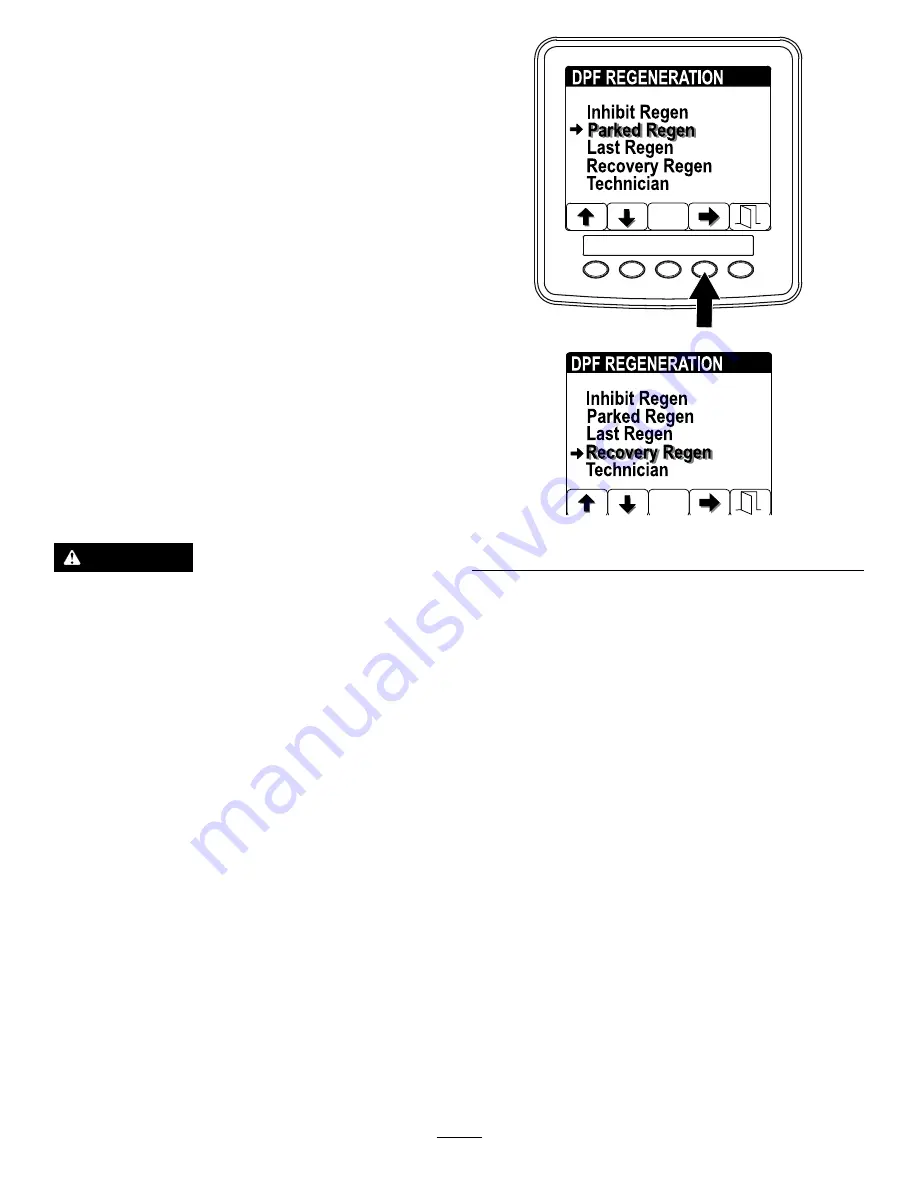
1.

Access the DPF Regeneration menu, and press
buttons 1 or 2 to scroll down to the P

ARKED

R

EGEN

option or the R

ECOVERY

R

EGEN

option

(

Figure 54

).

g241869

g241870

Figure 54

2.

Press the button 4 to select the Parked Regen
entry or the Recovery Regen entry (

Figure 55

).

3.

On the Parked Regen menu or Recovery
Regen menu, press the button 4 to start the
regeneration (

Figure 55

).

49


Summary of Contents for 31698

Page 1: ...rm No 3440 765 Rev A Groundsmaster 5900 or 5910 Rotary Mower Model No 31698 Serial No 407050000 and Up Model No 31699 Serial No 407050000 and Up Register at www Toro com Original Instructions EN 3440 765 ...

Page 2: ...rass on well maintained lawns in parks golf courses sports fields along roadways and on commercial grounds Using this product for purposes other than its intended use could prove dangerous to you and bystanders Read this information carefully to learn how to operate and maintain your product properly and to avoid injury and product damage You are responsible for operating the product properly and ...

Page 3: ...57 General Safety 57 Understanding the Audible Alarm 57 Pushing or Towing the Machine 58 Identifying the Tie Down Points 59 Hauling the Machine 59 Maintenance 60 Maintenance Safety 60 Recommended Maintenance Schedule s 60 Daily Maintenance Checklist 62 Pre Maintenance Procedures 63 Using the Battery Disconnect Switch 63 Raising the Machine 63 Removing and Installing the Inner Wing Deck Covers 64 L...

Page 4: ...N ISO 5395 when you complete the setup procedures and install the CE kit per the Declaration of Conformity General Safety This product is capable of amputating hands and feet and of throwing objects Always follow all safety instructions to avoid serious personal injury Read and understand the contents of this Operator s Manual before starting the engine Use your full attention while operating the ...

Page 5: ...6 93 6686 1 Hydraulic fluid 2 Read the Operator s Manual decal93 6687 93 6687 1 Do not step here decal93 7818 93 7818 1 Warning read the Operator s Manual for instructions on torquing the blade bolt nut to 115 to 149 N m 85 to 110 ft lb decal106 6754 106 6754 1 Warning do not touch the hot surface 2 Cutting dismemberment hazard fan entanglement hazard belt stay away from moving parts decal114 0849...

Page 6: ...d decal117 3276 117 3276 1 Engine coolant under pressure 3 Warning do not touch the hot surface 2 Explosion hazard read the Operator s Manual 4 Warning read the Operator s Manual decal117 4766 117 4766 1 Cutting dismemberment hazard fan stay away from moving parts keep all guards and shields in place decal117 4979 117 4979 1 Entanglement hazard belt stay away from moving parts keep all guards and ...

Page 7: ...de stay away from moving parts keep all guards and shields in place decal125 9688 125 9688 1 Off 3 On 2 Windshield wipers 4 Spray windshield washer fluid decal127 0392 127 0392 1 Warning keep away from hot surfaces decal130 0594 130 0594 Model with Cab Only 1 Warning read the Operator s Manual when sitting in the cab always wear a seat belt wear hearing protection decal130 0611 130 0611 1 Warning ...

Page 8: ...attery do not service the battery with the engine running 4 Positive terminal 2 Battery disconnect 5 Negative terminal 3 Battery connect 6 Read the Operator s Manual for more information on servicing the battery decal132 1316 132 1316 1 Entanglement hazard belt keep away from moving parts decal132 1318 132 1318 1 Attention read the Operator s Manual for information on fuses 8 ...

Page 9: ...rake pull up the black knob the manual valve resets when you start the engine decal132 3600 132 3600 Model with Cab Only 1 Read the Operator s Manual for more information on fuses 5 Working light 20 A 2 Headlight 25 A 6 Auxiliary power 15 A 3 Condenser fan and A C clutch 30 A 7 Cab light 15 A 4 Fan 25 A 8 Windshield wipers 15 A decal133 0980 133 0980 Model with Cab Only 1 Head light on 4 Overhead ...

Page 10: ... eye protection explosive gases can cause blindness and other injuries 3 Caustic liquid chemical burn hazard 8 Battery acid can cause blindness or severe burns 4 Wear eye protection 9 Flush eyes immediately with water and get medical help fast 5 Read the Operator s Manual 10 Contains lead do not discard decal140 5829 140 5829 1 Read the Operator s Manual for information on fuses 6 Electric seat 10...

Page 11: ...ts with the maximum recommended slope indicated on the decal Review the instructions for operating the machine on slopes in the Operator s Manual as well as the conditions in which you would operate the machine to determine whether you can operate the machine in the conditions on that day and at that site Changes in the terrain can result in a change in slope operation for the machine 1 Warning re...

Page 12: ...decal121 8378 121 8378 Model with Cab Only 1 Fan off 3 Cold air 5 External air 7 Air conditioner on 2 Fan on full 4 Hot air 6 Internal air 8 Air conditioner off 12 ...

Page 13: ...t the attachment left 8 Engine run electric preheat 3 Parking brake on 6 Pivot the attachment right 9 Engine start decal131 6027 131 6027 1 Height of cut settings 3 Lower caster position heights of cut 76 to 153 cm 3 to 6 inches 2 Upper caster position heights of cut 25 to 102 cm 1 to 4 inches 13 ...

Page 14: ...un position 4 Turn the key to the engine start position 5 To disengage the PTO push down the knob 3 To shut off the engine 1 Move the throttle switch to slow 2 Disengage the PTO 3 Engage the parking brake 4 Wait 5 minutes 5 Turn the ignition key to Stop and 6 Remove the key 6 To switch the transmission to high speed fully raise the attachments and switch the speed control to the HIGH position 14 ...

Page 15: ...utting unit off 2 Beacon 8 Lower the left cutting unit 3 Work light 9 Lower the center cutting unit 4 Engine speed 10 Lower the right cutting unit 5 Transmission 11 Horn 6 Cutting unit on decal139 0977 139 0977 1 Read the Operator s Manual 15 ...

Page 16: ... required Check the fluid levels 7 No parts required Grease the machine 8 Production year decal 1 Install the decal CE machines only Media and Additional Parts Description Qty Use Operator s Manual 1 Review it before operating the machine Engine owner s manual 1 Use it to reference engine information Declaration of conformity 1 For CE compliance Ignition keys 2 Start the engine Note Determine the ...

Page 17: ...ote Leave the eccentrics positioned between the deck mounts 3 Lower the winglet to the operating position 4 Install the front and rear stop bolts through the upper mounting holes and eccentrics Figure 4 Note Ensure that the stop bolt engages the tab on the hinge pin g008868 Figure 4 1 Winglet 4 Eccentric 2 Hinge pin 5 Lower hole 3 Bolt 5 Install the nuts securing the stop bolts Note Do not tighten...

Page 18: ...es Important Traction performance including tire slip control is dependent on the ratio of the tire size between the front and rear tires Use only genuine Toro tires 4 Leveling the Front Center Cutting Unit No Parts Required Procedure Note Perform this procedure on a flat level surface Refer to Adjusting the Height of Cut page 30 1 Rotate the blade on each outer spindle until the ends face forward...

Page 19: ...N m 110 ft lb 6 Adjust the forward eccentric until it just makes contact with the inner slot surface of the winglet pivot brackets 7 Tighten the bolt and nut for this eccentric to 149 N m 110 ft lb 8 Repeat the procedure on the opposite winglet 6 Checking the Fluid Levels No Parts Required Procedure 1 Check the engine oil level before starting the engine refer to Checking the Engine Oil Level page...

Page 20: ...ts needed for this procedure 1 Production year decal Procedure On machines requiring CE compliance install the production year decal included in the loose parts and the CE Kit sold separately Figure 9 g282517 Figure 9 1 Production year decal 20 ...

Page 21: ...Product Overview g031657 Figure 10 1 Wing cutting unit 5 Fuel tank 2 Control panel 6 Steering wheel 3 Roll bar 7 Front cutting unit 4 Hood 8 InfoCenter 21 ...

Page 22: ...itch to activate the right turn signal Figure 11 Note The center position is off Key Switch The key switch has 3 positions STOP RUN PREHEAT and START Figure 11 PTO Switch The PTO switch has 2 positions OUT start and IN stop Pull out the PTO button to engage the implement or mower deck blades Push in the button to disengage the implement operation Figure 11 High Low Range Speed Switch Press the fro...

Page 23: ...lever 2 Weight adjustment lever 5 Armrest adjustment knob 3 Seat adjustment lever Armrest Adjustment Knob Rotate the knob to adjust the armrest angle Figure 12 Seat Back Adjustment Lever Move the lever to adjust the seat back angle Figure 12 Weight Gauge The weight gauge indicates when the seat is adjusted to the weight of the operator Figure 12 Adjust the height by positioning the suspension with...

Page 24: ... Rotate the temperature control knob to regulate the air temperature in the cab Figure 13 Windshield Wiper Switch Use this switch to turn the windshield wipers on or off Figure 13 Air Conditioning Switch Use this switch to turn the air conditioning on or off Figure 13 Windshield Latch Lift up the latches to open the windshield Figure 14 Press in the latch to lock windshield to the OPEN position Pu...

Page 25: ...o change without notice g200003 Figure 15 Description Figure 15 reference Dimension or Weight Height with cab C 240 cm 94 5 inches Height with roll bar I 216 cm 85 inches Overall length F 442 cm 174 inches Length for storage or transport G 434 cm 171 inches 25 ...

Page 26: ...with cab 3313 kg 7 304 lb Net weight with roll bar 3044 kg 6 710 lb Attachments Accessories A selection of Toro approved attachments and accessories is available for use with the machine to enhance and expand its capabilities Contact your Authorized Service Dealer or authorized Toro distributor or go to www Toro com for a list of all approved attachments and accessories To ensure optimum performan...

Page 27: ...care in handling fuel It is flammable and its vapors are explosive Extinguish all cigarettes cigars pipes and other sources of ignition Use only an approved fuel container Do not remove the fuel cap or fill the fuel tank while the engine is running or hot Do not add or drain fuel in an enclosed space Do not store the machine or fuel container where there is an open flame spark or pilot light such ...

Page 28: ...ng and reduces fuel filter plugging Using summer grade fuel above 7 C 20 F contributes toward longer fuel pump life and increased power compared to winter grade fuel Using Biodiesel This machine can also use a biodiesel blended fuel of up to B20 20 biodiesel 80 petrodiesel Sulfur content Ultra low sulfur 15 ppm Biodiesel fuel specification ASTM D6751 or EN14214 Blended fuel specification ASTM D975...

Page 29: ...f cut and proper machine performance Do not underinflate the tires Check the air pressure in all the tires before operating the machine Traction performance including tire slip control is dependent on the ratio of the tire size between the front and rear tires Use only genuine Toro tires g001055 Figure 17 Checking the Caster Wheel Tire Pressure The correct air pressure in the caster wheel tires is...

Page 30: ... the bottom caster fork hole When operating the machine at a height of cut lower than 76 mm 3 inches and when you detect grass buildup reverse the direction of the machine to pull any clippings away from the wheel and fork g031660 Figure 18 1 Caster wheel height of cut mounting holes 2 Caster fork height of cut spacers 4 Using the supplied caster cap wrench loosen the tensioning cap and remove it ...

Page 31: ...s refer to the chart to determine the correct holes for the height of cut setting Figure 22 Note To prevent grass buildup between the wheel and the fork operate the machine at the 76 mm 3 inches height of cut or higher and install the axle bolt in the bottom caster fork hole When operating the machine at a height of cut lower than 76 mm 3 inches and when you detect grass buildup reverse the direct...

Page 32: ...ing at heights of cut greater than 51 mm 2 inches and in the higher position when operating at heights of cut lower than 51 mm 2 inches Adjust the inner skids Figure 24 Important Torque the screw at the front of each inner skid to 9 to 11 N m 80 to 100 in lb g032003 Figure 24 Adjusting the Outer Skids Mount the outer skids in the lower position when operating at heights of cut greater than 51 mm 2...

Page 33: ...r position when operating at heights of cut lower than 51 mm 2 inches Adjusting the Roller 1 Remove the roller shaft screw and nut securing the roller to the deck bracket Figure 26 g033107 Figure 26 1 Roller 2 Roller shaft screw and nut 2 Align the roller with the top holes and install the shaft with the screw and nut Figure 27 g033108 Figure 27 1 Roller 2 Roller shaft screw and nut 33 ...

Page 34: ...forks to match the desired height of cut 3 Measure from the floor to the front tip of the mowing blade 4 Rotate the blade 180 and measure from the floor to the tip of the mowing blade Note The rear of the blade should be 7 5 mm 0 3 inch higher than the front Note If you need to make an adjustment adjust the shims on the rear caster forks Matching the Height of Cut Between Cutting Units 1 Position ...

Page 35: ...still too low add an additional shim to the bottom of front inside caster arm of the wing cutting unit and 1 shim to the front outside caster arm of the wing cutting unit 9 Once the mowing height matches at the edges of the front and wing cutting units verify that the cutting unit unit pitch is still 7 6 mm 0 3 inch Adjusting the Mirrors For Machines with a Cab Rear View Mirror While sitting in th...

Page 36: ...ction in the interlock system that you should correct before resuming operation Checking the PTO Safety Interlock Function 1 Start the engine 2 With the engine running rise from the seat and engage the PTO Note The PTO should not engage If it does engage there is a malfunction in the interlock system that you should correct before resuming operation 3 Sit on the seat and disengage the PTO 4 With t...

Page 37: ...stop before adjusting the height of cut unless you can adjust it from the operating position Operate the engine only in well ventilated areas Exhaust gases contain carbon monoxide which is lethal if inhaled Never leave a running machine unattended Before you leave the operator s position do the following Park the machine on a level surface Disengage the power takeoff and lower the attachments Enga...

Page 38: ...ese can change the stability of the machine and cause a loss of control Starting the Engine 1 Ensure that the parking brake is engaged 2 Remove your foot from the traction pedal and ensure that it is in the NEUTRAL position 3 Turn the ignition key to the RUN position 4 When the glow indicator dims turn the ignition key to the START position 5 Release the key immediately when the engine starts and ...

Page 39: ...ilter so that filtered engine exhaust flows out the DPF The engine computer monitors the accumulation of soot by measuring the back pressure in the DPF If the back pressure is too high soot is not incinerating in the soot filter through normal engine operation To keep the DPF clear of soot remember the following Passive regeneration occurs continuously while the engine is running run the engine at...

Page 40: ...n The lighter ash is discharged through the exhaust system the heavier ash collects in the soot filter Ash is a residue of the regeneration process Over time the diesel particulate filter accumulates ash that does not discharge with the engine exhaust The computer for the engine calculates the amount of ash accumulated in the DPF When enough ash accumulates the engine computer sends information to...

Page 41: ... Oxidation Catalyst DOC and the Soot Filter page 71 Level 2 Engine Warning g243501 Figure 33 Check Engine SPN 3720 FMI 16 None The computer de rates the engine power to 50 Service the DPF refer to Servicing the Diesel Oxidation Catalyst DOC and the Soot Filter page 71 Level 3 Engine Warning g243500 Figure 34 Check Engine SPN 3251 FMI 0 Engine speed at maximum torque 200 rpm The computer de rates t...

Page 42: ... soot level When the high exhaust temperature icon is displayed in the InfoCenter a regeneration is in progress During reset regeneration the engine computer adjusts the engine settings to raise the exhaust temperature Reset Refer to Reset Regeneration page 45 Types of diesel particulate filter regeneration that require you to park the machine Type of Regeneration Conditions that cause DPF regener...

Page 43: ... a parked regeneration and continued operating the machine adding more soot to the DPF Refer to Parked or Recovery Regeneration page 47 Accessing the DPF Regeneration Menus Accessing the DPF Regeneration Menus 1 Access the Service menu and press buttons 1 or 2 to scroll to the DPF REGENERATION option Figure 35 g241798 Figure 35 2 Press the button 4 to select the DPF Regeneration entry Figure 35 Ti...

Page 44: ...e of DPF operation Figure 39 g241815 Figure 39 DPF Operation Table State Description Normal The DPF is in normal operating mode passive regeneration Assist Regen The engine computer is performing an assist regeneration The regen inhibit setting is set to ON Reset Stby The engine computer is trying to run a reset regeneration but 1 of the following conditions prevents regeneration The exhaust tempe...

Page 45: ...eration Reset Regeneration CAUTION The exhaust temperature is hot approximately 600 C 1 112 F during DPF regeneration Hot exhaust gas can harm you or other people Never operate the engine in an enclosed area Make sure that there are no flammable materials around the exhaust system Never touch a hot exhaust system component Never stand near or around the exhaust pipe of the machine g241828 Figure 4...

Page 46: ...egeneration Important When you shut off the engine and start it again the inhibit regen setting defaults to OFF 1 Access the DPF Regeneration menu and press buttons 1 or 2 to scroll down to the INHIBIT REGEN option Figure 43 g241830 Figure 43 2 Press the button 4 to select the Inhibit Regen entry Figure 43 3 Press the button 4 to change the inhibit regeneration setting from On to Off Figure 44 or ...

Page 47: ...llowing messages display in the InfoCenter Engine warning SPN 3720 FMI 16 Figure 48 g243501 Figure 48 Parked regeneration required ADVISORY 1212 Figure 49 Note Advisory 1212 displays every 15 minutes g241835 Figure 49 If you do not perform a parked regeneration within 2 hours the InfoCenter displays parked regeneration required power takeoff disabled ADVISORY 1213 Figure 50 g241836 Figure 50 Impor...

Page 48: ... Parked or Recovery Regeneration page 47 Note The Home screen displays the power takeoff disabled ADVISORY 1214 every 15 minutes until you perform a recovery regeneration DPF Status Limitation If the engine computer requests a recovery regeneration or is processing a recovery regeneration and you select the PARKED REGEN option Figure 52 Parked Regen screen locks unavailable g241999 g241997 Figure ...

Page 49: ...orming a Parked or Recovery Regeneration CAUTION The exhaust temperature is hot approximately 600 C 1 112 F during DPF regeneration Hot exhaust gas can harm you or other people Never operate the engine in an enclosed area Make sure that there are no flammable materials around the exhaust system Never touch a hot exhaust system component Never stand near or around the exhaust pipe of the machine Im...

Page 50: ...g the parked regeneration or 1 2 tank of fuel if you are performing the recovery regeneration and press the button 4 to continue Figure 56 g241894 g241895 Figure 56 5 At the DPF checklist screen verify that the parking brake is engaged that the engine speed is set to low idle press the button 4 to continue Figure 57 50 ...

Page 51: ...the INITIATE DPF REGEN screen press the button 4 to continue Figure 58 g241900 g241901 Figure 58 7 The InfoCenter displays the INITIATING DPF REGEN message Figure 59 Note If needed press button 4 to cancel the regeneration process 51 ...

Page 52: ...information The InfoCenter may display the following messages found in the table that follows Check Message and Corrective Action Table Parked Regen Recovery Regen Check Message Less that 50 hours since last regeneration press any key Corrective Action Exit the regeneration menu and run the machine until the time since last regeneration is greater than 50 hours refer to Time Since Last Regeneratio...

Page 53: ... to low idle Parked Regen Recovery Regen Check Message Regen rejected by engine 1217 press any key Corrective Action Troubleshoot the engine computer condition and retry DPF regeneration 10 The InfoCenter displays the home screen and the regeneration acknowledge icon Figure 61 appears in the lower right corner of the screen as the regeneration processes g241917 Figure 61 Note While the DPF regener...

Page 54: ...ess the DPF Regeneration menu and press buttons 1 or 2 to scroll down to the PARKED REGEN option or the RECOVERY REGEN option Figure 64 g241999 g242000 Figure 64 2 Press the button 4 to cancel a Parked Regen or cancel a Recovery Regen Figure 65 g242002 g242003 Figure 65 Note If you do not want to cancel the parked or recovery regeneration press button 5 to exit the regeneration screen 54 ...

Page 55: ...he highest position and press the traction pedal slowly but fully to attain maximum ground speed Before stopping the engine disengage all controls and decrease the engine speed to LOW IDLE 1 000 rpm Turn the ignition key to the OFF position to shut off the engine Before transporting the machine raise the cutting units and secure the transport latches on the wing cutting unit Figure 66 g008846 Figu...

Page 56: ...n engage the transport latches and place the throttle in the FAST position Changing Mowing Patterns Change mowing patterns often to minimize a poor after cut appearance from repeatedly mowing in the same direction Understanding Counterbalance The counterbalance system maintains hydraulic back pressure on the cutting unit lift cylinders This pressure improves traction by transferring the cutting un...

Page 57: ...etween the roof and the headliner and correct it as needed Measure the air temperature at the front center vent in the headliner This should typically stabilize at less than or equal to 10 C 50 F Refer to the Service Manual for additional information After Operation General Safety Shut off the engine remove the key and wait for all movement to stop before you leave the operator s position Allow th...

Page 58: ...h tow valves on the hydrostatic transmission 3 Rotate each valve 3 turns counter clockwise to open the valve and allow the fluid to bypass internally 4 Manually release the automatic parking brake using the bypass valve and plunger as shown in Figure 70 g311881 Figure 70 5 Push or tow the machine 6 Finish pushing or towing the machine and close the bypass valve Torque the valve to 70 N m 52 ft lb ...

Page 59: ...he machine on the bumper Figure 73 g009005 Figure 73 1 Rear tie downs Hauling the Machine Remove the key and shut off the fuel if equipped before storing or hauling the machine Use care when loading or unloading the machine into a trailer or a truck Use full width ramps for loading the machine into a trailer or a truck Tie the machine down securely 59 ...

Page 60: ...elease pressure from components with stored energy Keep all parts of the machine in good working condition and all hardware tightened especially blade attachment hardware Replace all worn or damaged decals To ensure safe optimal performance of the machine use only genuine Toro replacement parts Replacement parts made by other manufacturers could be dangerous and such use could void the product war...

Page 61: ...id replace the hydraulic filter sooner if the service interval indicator is in the red zone Every 1 000 hours Check and adjust the intake and exhaust valve clearance Calibrate the traction pedal Check the rear wheel toe in Check the 24 V alternator belt and AC compressor belt tension Replace the blade drive belts If you are using the recommended hydraulic fluid replace the hydraulic filter sooner ...

Page 62: ... debris and blow out with compressed air Check for unusual operating noises Check the hydraulic system fluid level Check the hydraulic hoses for damage Check for fluid leaks Check the fuel level Check the tire and caster pressure Check the instrument operation Check the height of cut adjustment Lubricate all of the grease fittings 2 Clean the machine Touch up any damaged paint 1Check the glow plug...

Page 63: ... Important Do not turn the battery disconnect switch to the OFF position while the engine is running Ensure that the machine is shut off before turning the battery disconnect switch to the OFF position as you may cause damage to the engine and or machine g031667 Figure 74 1 Battery disconnect switch OFF position 2 Battery disconnect switch ON position Raising the Machine Use the following as point...

Page 64: ...ard approximately 2 5 cm 1 inch 2 Disengage these cover edges 6 Lift the front edge and guide it between the lift arm and the roller to remove it Figure 79 g013894 Figure 79 1 Slide the cover out between the lift arm and roller Installing the Inner Wing Deck Covers 1 Lower the wing deck onto a level surface 2 Slide the cover into position by guiding the rear edge between the lift arm and the rolle...

Page 65: ...ium grease Also lubricate the machine immediately after every washing Traction Unit 2 impact arms Figure 80 2 front deck lift cylinder pivots Figure 80 2 side deck lift cylinder pivots Figure 80 4 steering cylinder ball joints Figure 81 2 tie rod ball joints Figure 81 2 king pin bushings Figure 81 1 rear axle pivot bushing Figure 82 g031674 Figure 80 g008855 Figure 81 g009249 Figure 82 65 ...

Page 66: ...83 Front Lift Assemblies 2 lift arm bushings Figure 84 2 lift arm ball joints Figure 84 2 front deck lift cylinder pivots Figure 84 g009247 Figure 84 Wing Cutting Units Each Wing 4 caster fork shaft bushing Figure 85 3 spindle shaft bearings located on the spindle housing as shown in Figure 85 2 idler arm pivot bushings located on the idler pivot shaft as shown in Figure 85 g009151 Figure 85 Wing ...

Page 67: ...ntake system for leaks damage or loose hose clamps Also inspect the rubber intake hose connections at the air cleaner and turbocharger to ensure that the connections are complete Service the air cleaner filter only when the Check Air Filter message is displayed on the InfoCenter Figure 88 Changing the air filter before it is necessary only increases the chance of dirt entering the engine when you ...

Page 68: ...cleaner body 3 Before removing the filter use low pressure air 275 kPa or 40 psi clean and dry to help remove large accumulations of debris packed between the outside of the primary filter and the canister Note Avoid using high pressure air that could force dirt through the filter into the intake This cleaning process prevents debris from migrating into the intake when the primary filter is remove...

Page 69: ...ith fuel If the engine oil level is above the Full mark change the engine oil The best time to check the engine oil is when the engine is cool before it has been started for the day If it has already been run allow the oil to drain back down to the sump for at least 10 minutes before checking If the oil level is at or below the Add mark on the dipstick add oil to bring the oil level to the Full ma...

Page 70: ...g031551 g031336 Figure 94 4 Change the engine oil filter Figure 95 Note Ensure that the oil filter gasket touches the engine and then an extra 3 4 turn is completed g031260 g031261 Figure 95 70 ...

Page 71: ...ervice Interval Every 2 000 hours For information on lapping or adjusting the engine intake and exhaust valves refer to your engine owner s manual Inspecting and Cleaning Engine Emission Control Components and Turbocharger Service Interval Every 3 000 hours For information on inspecting and cleaning the engine emission control components refer to your engine operator s manual Servicing the Diesel ...

Page 72: ...ry 800 hours Drain and clean the fuel tank Before storage Drain and clean the fuel tank In addition to the listed service interval drain and clean the tank if the fuel system becomes contaminated or if you are storing the machine for an extended period Use clean fuel to flush out the tank Inspecting the Fuel Lines and Connections Service Interval Every 400 hours Yearly whichever comes first Inspec...

Page 73: ...o that the electric fuel pump can fill the new filter 9 When fuel flows from the vent plug close the vent plug start the engine and check for leaks Note Correct as necessary with the engine off Replacing the Fuel Filter Element Service Interval Every 500 hours Replace the fuel filter element 1 Clean the area around the fuel filter head Figure 99 g031734 Figure 99 1 Fuel filter head 2 Filter 2 Remo...

Page 74: ...cause a dirty battery discharges slowly To clean the battery wash the entire case with a solution of baking soda and water Rinse with clear water Coat the battery posts and cable connectors with Grafo 112X skin over grease Toro Part No 505 47 or petroleum jelly to prevent corrosion Locating the Fuses Important If you are installing an auxiliary accessory to the machine the only approved locations ...

Page 75: ...re 103 1 Fuse block g033290 Figure 104 1 Fuse block 2 Power leads The cab fuses Figure 105 are located in the fuse box on the cab headliner Figure 106 g031740 Figure 105 g032673 Figure 106 1 Cab fuse box 2 Fuses 75 ...

Page 76: ...mp post Figure 108 g033269 Figure 108 1 Positive jump post 3 Negative jumper cable clamp 2 Negative jump post 4 Positive jumper cable clamp 5 Connect the negative lead of the battery charger to the negative jump post Figure 108 6 Connect the battery charger to the electrical source and charge the battery according to the Battery charging Table that follows Important Do not overcharge the battery B...

Page 77: ...rter motor stops turning Do not operate the starter motor for more than 30 seconds at one time Wait 30 seconds before operating the starter motor to cool the motor 7 When the engine starts have the other person disconnect the negative jumper cable from the negative jump post and then disconnect the positive jumper cable Figure 109 Removing the Batteries 1 Open the hood and turn the battery disconn...

Page 78: ...ery cables from the batteries 8 Remove the fasteners that secure the battery hold downs 9 Carefully remove the batteries from the machine Figure 113 g199822 Figure 113 1 Battery cover 6 Cable assembly for 24 VDC system 2 Battery disconnect switch 7 Cable jumper for 24 VDC system 3 Batteries 12 V for 12 VDC system 8 Ground cable 4 Batteries 12 V for 24 VDC system 9 Battery hold down 5 Positive cabl...

Page 79: ... the battery disconnect switch to the ON position Drive System Maintenance Calibrating the Traction Pedal Service Interval Every 1 000 hours Calibrate the traction pedal Contact your autorized Toro distributor or refer to the Toro Service Manual for assistance Adjusting the Traction Pedal Angle You can adjust the operating angle of the traction pedal for your comfort 1 Loosen the 2 nuts and bolts ...

Page 80: ...parts can cause severe burns Always allow the engine to cool at least 15 minutes before removing the radiator cap Use a rag when opening the radiator cap and open the cap slowly to allow steam to escape Do not operate the machine without the covers in place Keep your fingers hands and clothing clear of rotating fan and drive belt Checking the Engine Cooling System Service Interval Before each use ...

Page 81: ...y or alcohol methanol based coolants 4 Install the radiator cap and expansion tank cap Cleaning the Cooling Systems Service Interval Before each use or daily Perform the pre maintenance procedure refer to Maintenance Safety page 60 Important Do not use water to clean the radiator core or hydraulic fluid cooler core Cleaning the radiator core or hydraulic fluid cooler core with water can promote pr...

Page 82: ... and lock the prop rod into the notch Figure 120 g033289 Figure 120 1 Hydraulic fluid cooler 3 Prop rod 2 Hydraulic cooling fans Changing the Engine Cooling System Fluid Service Interval Every 2 000 hours Every 2 years whichever comes first Flush the engine cooling system and replace the fluid The capacity of the system on a machine without a cab is 10 4 L 13 5 US qt and with a cab is 17 L 18 US q...

Page 83: ...oler Figure 123 g034935 Figure 123 1 Coolant hose 8 After draining the engine coolant close the drain valve on the radiator drain hose and connect the coolant hose 9 Remove the cap of the expansion tank and fill it to the Low mark with engine coolant Install the cap 10 Start and run the engine until it reaches operating temperature 11 Check the engine coolant level refer to Checking the Engine Coo...

Page 84: ...ng when the belt is rotating blades slipping when cutting grass frayed edges burn marks and cracks Replace the belt if any of these signs occur Replacing the Front Cutting Unit Belts 1 Lower the cutting unit to the floor 2 Remove the belt covers from the top of the cutting unit and set the covers aside 3 On the front deck center position loosen the jam nuts on the idler pulley stop screw and threa...

Page 85: ... the covers aside 3 Remove the bolts securing the hydraulic motor to the cutting unit Figure 125 4 Lift the motor off the cutting unit and lay it on top of the cutting unit 5 Using a ratchet wrench or similar tool move the idler pulleys away from the drive belt to release the belt tension and allow the belt to slip off the pulleys Figure 127 g009009 Figure 127 1 Idler pulleys 6 Remove the old belt...

Page 86: ... for damage caused by improper substitutions so use products only from reputable manufacturers who will stand behind their recommendation High Viscosity Index Low Pour Point Anti wear Hydraulic Fluid ISO VG 46 Material Properties Viscosity ASTM D445 cSt 40 C 104 F 44 to 48 High Viscosity Index Low Pour Point Anti wear Hydraulic Fluid ISO VG 46 cont d Viscosity Index ASTM D2270 140 or higher Pour P...

Page 87: ...change the hydraulic fluid 1 Park the machine on a level surface engage the parking brake lower the cutting deck shut off the engine and remove the key 2 Place a large drain pan under the hydraulic fluid tank 3 Remove the hydraulic tank cap and dipstick 4 Remove the drain plug from the bottom of the tank and let the hydraulic fluid flow into the pan Figure 132 g031319 Figure 132 1 Hydraulic filter...

Page 88: ...Fluid page 86 Important Use only the hydraulic fluids specified Other fluids could cause system damage 7 Install the reservoir dipstick and cap 8 Start the engine and use all of the hydraulic controls to distribute hydraulic fluid throughout the system Note Also check for leaks then shut off the engine 9 Check the fluid level and add enough to raise the level to the Full mark on the dipstick Note ...

Page 89: ...intenance Procedures page 63 3 Remove the retainer clip and disconnect the damper assembly from the cutting unit Figure 133 g008980 Figure 133 1 Damper assembly 2 Retainer clip 4 Remove the hairpin cotter and clevis pin securing the height of cut chains to the rear of the cutting unit Figure 134 g008979 Figure 134 1 Height of cut chain 3 Hairpin cotter 2 Clevis pin 5 Start the engine slowly raise ...

Page 90: ...Ensure that the winglets are level to the front deck and the front deck is level side to side Adjusting the Front Cutting Unit Pitch 1 Rotate each blade so that they point straight forward Figure 136 g009150 Figure 136 1 Use 1 of these blades for measuring the front blade height 2 Use 1 of these blades for measuring the rear blade height 2 Using a short ruler measure from the floor to the front ti...

Page 91: ...itch Servicing the Caster Wheels and Bearings Service Interval Every 500 hours Inspect the cutting unit caster wheel assemblies 1 Remove the locknut from the bolt holding the caster wheel assembly between the caster fork or the caster pivot arm Figure 139 g004738 Figure 139 1 Caster wheel 3 Bearing 2 Caster fork 4 Bearing spacer 2 Grasp the caster wheel and slide the bolt out of the fork or pivot ...

Page 92: ...ge of the blade at the same position as in step 4 Note The difference between the dimensions obtained in steps 4 and 5 must not exceed 3 mm 1 8 inch If the dimension exceeds 3 mm 1 8 inch the blade is bent and must be replaced refer to Removing and Installing the Cutting Unit Blade s page 92 Removing and Installing the Cutting Unit Blade s Replace the blade if it hits a solid object is out of bala...

Page 93: ...Sharpen the cutting edges if they are dull or nicked Figure 143 g000276 Figure 143 1 Sharpen at the original angle Note Sharpen only the top of the cutting edge and maintain the original cutting angle to ensure the sharpness Note The blade will remain balanced if the same amount of metal is removed from both cutting edges Note Remove the blades and sharpen them on a grinder After sharpening the cu...

Page 94: ... 4 Do not pressure wash under the rear overhang Cleaning the Cab Air Filters Service Interval Every 250 hours 1 Remove the screws and grates from both the in cab and rear cab air filters Figure 145 and Figure 146 g028378 Figure 145 In Cab Air Filter 1 Filter 3 Screw 2 Grate g028379 Figure 146 Rear Cab Air Filter 1 Filter 3 Screw 2 Grate 2 Clean the filters by blowing clean oil free compressed air ...

Page 95: ...re 147 1 Latch mount assembly 3 Screen cover 2 Latch Cleaning the Air Conditioning Assembly Service Interval Every 250 hours more frequently in extremely dusty or dirty conditions 1 Disconnect the wire for each fan g032323 Figure 148 Right fan shown 1 Fan 3 Knob 2 Wire 2 Remove the 2 knobs and remove the fan assembly 3 Open the 4 latches on the air conditioning assembly and remove the screen g0323...

Page 96: ...e negative terminal first and the positive last Always connect the positive terminal first and the negative last B Clean the battery terminals and posts with a wire brush and baking soda solution C Coat the cable terminals and battery posts with Grafo 112X skin over grease Part Number 505 47 or petroleum jelly to prevent corrosion D Slowly recharge the battery every 60 days for 24 hours to prevent...

Page 97: ...Notes ...

Page 98: ... for marketing purposes Retention of your Personal Information Toro will keep your personal information as long as it is relevant for the above purposes and in accordance with legal requirements For more information about applicable retention periods please contact legal toro com Toro s Commitment to Security Your personal information may be processed in the US or another country which may have le...

Page 99: ... to restaurants grocery stores hotels schools and hospitals and on a wide variety of products Additionally some online and mail order retailers provide Prop 65 warnings on their websites or in catalogs How do the California warnings compare to federal limits Prop 65 standards are often more stringent than federal and international standards There are various substances that require a Prop 65 warni...

Page 100: ...vered for the duration of the original product warranty and become the property of Toro Toro will make the final decision whether to repair any existing part or assembly or replace it Toro may use remanufactured parts for warranty repairs Deep Cycle and Lithium Ion Battery Warranty Deep cycle and Lithium Ion batteries have a specified total number of kilowatt hours they can deliver during their li...

Reviews: