


17
Controls
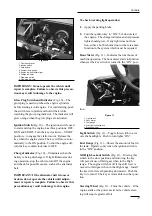
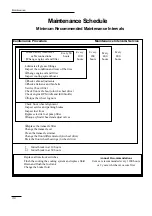
Figure 10
1. Tilt steering lever
2. Ignition switch
3. Horn button
4. Coolant temp. gauge
5. Engine low oil pressure light
6. Charge indicator
7. Glow plug switch
8. Glow plug indicator
IMPORTANT: Do not operate the vehicle until
repair is complete. Failure to observe this precau-
tion may result in damage to the engine.
Glow Plug Switch and Indicator (Fig. 10)—The
glow plug is used to preheat the engine cylinders
before starting a cold engine. For cold starting, push
the switch lever upward and hold it their while
watching the glow plug indicator. The indicator will
glow orange when the glow plugs are activated.
Ignition Switch (Fig. 10)—The ignition switch, used
to start and stop the engine, has three positions: OFF,
RUN and START. Turn the key clockwise—START
position—to engage the starter motor. Release the
key when the engine starts. The key will move auto-
matically to the ON position. To shut the engine off,
turn the key counterclockwise to OFF.
Charge Indicator (Fig. 10)—Illuminates when the
battery is being discharged. If light illuminates dur-
ing operation, stop the vehicle, turn Off the engine
and check for possible causes, such as the alternator
belt.
IMPORTANT: If the alternator belt is loose or
broken, do not operate the vehicle until adjust-
ment or repair is complete. Failure to observe this
precaution may result in damage to the engine.
To check warning light operation:
1. Apply the parking brake.
2. Turn the ignition key to “ON”, but do not start
the engine. The charge indicator and oil pressure
lights should glow. If any light does not func-
tion, either a bulb is burned out or there is a mal-
function in the system which must be repaired.
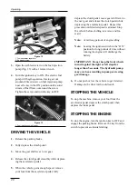
Hour Meter (Fig. 11)—Indicates the total hours of
machine operation. The hour meter starts to function
whenever the key switch is turned to the “ON” posi-
tion.
Figure 11
1. Light switch
2. Hour meter
3. Fuel gauge
4. 3rd High lockout switch
5. Steering wheel
Light Switch (Fig. 11)—Toggle this switch to acti-
vate the headlights. Push to turn lights “ON”.
Fuel Gauge (Fig. 11)—Shows the amount of fuel in
the tank. Operates only when the ignition switch is
in the “ON” position.
3rd High Lockout Switch (Fig. 11)—Moving this
switch to the slow position and removing the key
will prevent use of third gear when in the High
range. The engine will shut off if the shift lever is
moved to third gear when in the High range. Install
the key with its teeth pointing downward. Push the
key in to turn it. The key is removable in either posi-
tion.
Steering Wheel (Fig. 11)—Turns the vehicle. If the
engine stalls or the power assist fails, vehicle steer-
ing will require greater effort.
➀
➃
➄
➁
➂
➀
➃
➆
➄
➅
➇
➁
➂


