background image

16

Adjusting the Height-of-Cut

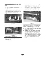
1. Verify that the rear roller is level and that the bedknife

to reel contact is correct. Tip the mower back on the
handle to expose the front and rear rollers and the
bedknife.

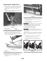
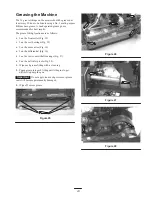
2. Loosen the locknuts securing the height-of-cut arms to

the height-of-cut brackets (Fig. 14).

1

4

2

3

Figure 14

1.

Height-of-cut arm

2.

Height-of-cut bracket

3.

Locknut

4.

Adjusting screw

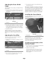
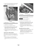
3. Loosen the nut on the gauge bar (Fig. 15) and set the

adjusting screw to the desired height-of-cut. The
distance between the bottom of the screw head and the
face of the bar is the height-of-cut.

1

2

3

Figure 15

1.

Gauge bar

2.

Height adjusting screw

3.

Nut

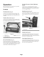
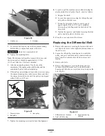
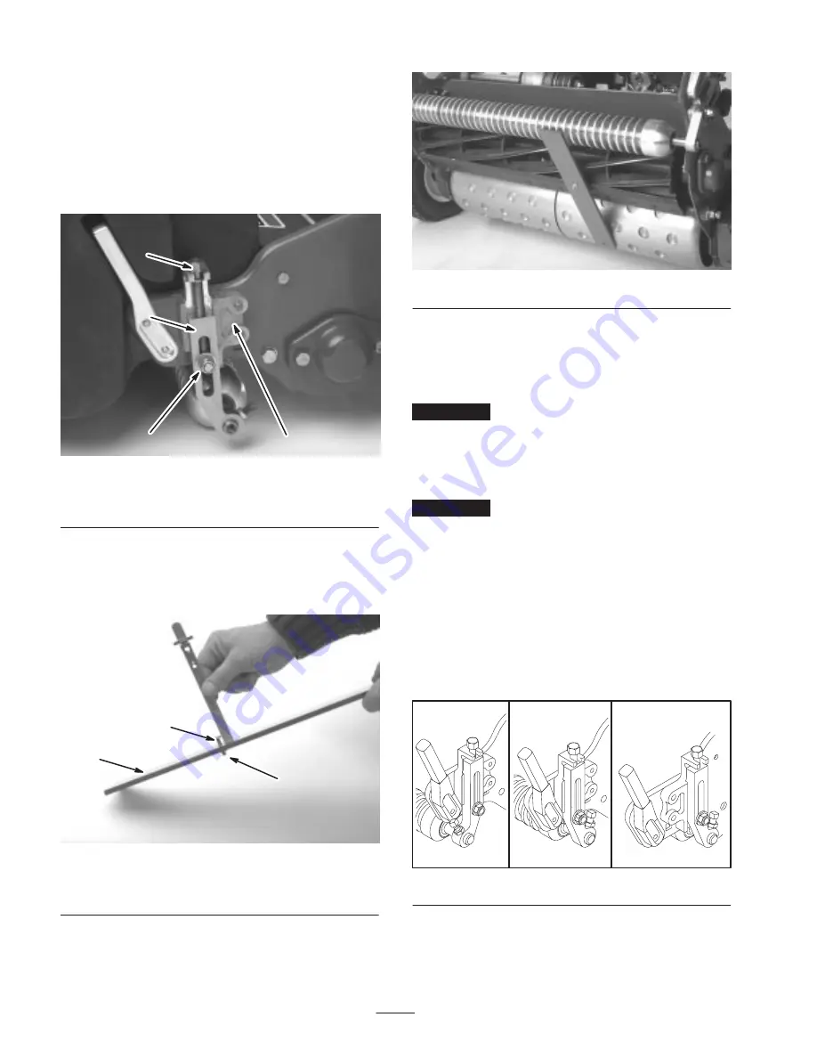
4. Hook the screw head on the cutting edge of the

bedknife and rest the rear end of the bar on the rear
roller (Fig. 16).

Figure 16

5. Rotate the adjusting screw until the roller contacts the

front of the gauge bar.

6. Adjust both ends of the roller until the entire roller is

parallel to the bedknife.

Important


When set properly, the rear and front rollers

will contact the gauge bar and the screw will be snug
against the bedknife. This ensures the height-of-cut is
identical at both ends of the bedknife.

7. Tighten nuts to lock the adjustment.

Important


To avoid scalping on undulating turf, ensure

that the roller supports are positioned rearward (the roller
closer to the reel).

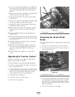
Note: The front roller can be put in three different positions
(Fig. 17), depending on the application and needs of the
user.

Use the front position when a groomer is installed.

Use the middle position without a groomer.

Use the third position in extremely undulating turf
conditions.

Figure 17

Summary of Contents for 04048

Page 1: ...ual English EN GB Form No 3350 250 Rev A Greensmaster 800 1000 and 1600 Greensmaster Mower Model No 04048 Serial No 240000001 and Up Model No 04052 Serial No 240000001 and Up Model No 04060 Serial No 240000001 and Up ...

Page 2: ...9 Adjusting the Interlock Switch 30 Servicing the Bedbar Greensmaster 800 1600 only 30 Servicing the Bedbar Greensmaster 1000 only 30 Backlapping the Reel 31 The Toro General Commercial Products Warranty 32 Introduction Read this manual carefully to learn how to operate and maintain your product properly The information in this manual can help you and others avoid injury and product damage Althoug...

Page 3: ...l in containers specifically designed for this purpose Refuel outdoors only and do not smoke while refuelling Add fuel before starting the engine Never remove the cap of the fuel tank or add fuel while the engine is running or when the engine is hot If fuel is spilled do not attempt to start the engine but move the machine away from the area of spillage and avoid creating any source of ignition un...

Page 4: ...k inside a building where fumes may reach an open flame or spark Allow the engine to cool before storing in any enclosure To reduce the fire hazard keep the engine silencer battery compartment and fuel storage area free of grass leaves or excessive grease Check the grass catcher frequently for wear or deterioration Keep all parts in good working condition and all hardware and hydraulic fittings ti...

Page 5: ...ed Maintenance and Storage Check all fuel lines for tightness and wear on a regular basis Tighten or repair them as needed If the engine must be running to perform a maintenance adjustment keep hands feet clothing and any parts of the body away from the cutting unit attachments and any moving parts especially the screen at the side of the engine Keep everyone away To ensure safety and accuracy hav...

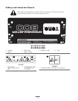
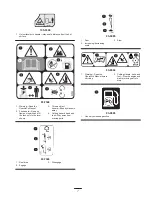
Page 6: ...lace any decal that is damaged or lost 105 5359 Model 04048 105 5360 Model 04052 105 5361 Model 04060 1 Disengage 2 Engage 3 Parking brake 4 Engage forward 5 Disengage neutral 6 Clutch 93 7273 1 Thrown object hazard Keep bystanders away 2 Cutting hazard hand and foot Stay away from moving parts 93 9356 1 Entanglement hazard Stay away from moving parts ...

Page 7: ...he level shown 3 Thrown object hazard Keep bystanders away 4 Cutting hazard hand and foot Stay away from moving parts 93 7346 1 Reel drive 2 Engage 3 Disengage 93 6085 1 Fast 2 Increasing decreasing scale 3 Slow 93 8064 1 Warning Read the Operator s Manual before servicing 2 Cutting Hazard hand and foot Stop the engine and wait for moving parts to stop 93 9886 1 Use only unleaded gasoline ...

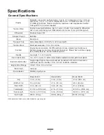
Page 8: ...hrottle lever traction engage lever and service park brake lever Mower has reel drive engage lever Safety devices neutral interlock system Handle Loop style 1 in 2 5 cm dia Reel Construction 5 in 12 7 cm dia 8 carbon steel blades welded to 6 stamped steel spiders Bedknife and Bedbar Single edged high carbon steel bedknife hardened to Rc 48 54 Fastened to machined cast iron bedbar 1 8 in 0 3 cm bed...

Page 9: ...8 7261 Part No 93 4262 Part No 94 5885 Full Roller Part No 104 2640 Part No 104 2642 Part No 95 0930 Wiehle Roller 43 spacing Part No 98 7264 Part No 88 6790 Swaged Roller Part No 52 3590 Auxiliary Roller KIt Part No 65 8560 Part No 65 8560 Wiehle Roller Scraper 43 spacing Part No 98 5920 01 Part No 65 8340 01 Part No 94 9012 01 Dethatching Reel Kit Model No 04111 Scraper Comb Part No 11 0070 Scra...

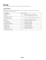
Page 10: ...ly Cable tie 1 2 Install the handle on the machine Secure the control cables to the handle Wheel Shaft right hand Wheel Shaft left hand 1 1 Use when installing optional transport wheels Spring 1 Mount kickstand Model 04060 only Grass basket 1 Install on the machine Operator s Manual 1 Read before operating Engine Owner s Manual 1 Read before operating Part s Catalog 1 Use for ordering parts Regist...

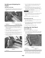
Page 11: ...screws and locknuts previously removed Fig 2 Ensure that you install the bushings in the handle arm mounting holes Important Do not overtighten the capscrews The handle arms must pivot freely 9 Secure the handle arms to the rear of the frame with the hairpin cotters and ring pins previously removed Fig 2 10 Secure the cables to the handle with cable ties Adjusting the Handle 1 Remove the hairpin c...

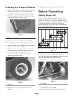
Page 12: ... axle shaft 1 Figure 5 1 Locking clip 8 Repeat the procedure on the opposite side of the machine 9 Inflate the tires to 12 to 15 psi 574 to 718 Pa Before Operating Adding Engine Oil Fill the crankcase with approximately 20 oz 0 6 l of proper viscosity oil before staring The engine uses any high quality oil having the American Petroleum Institute APl service classification SC SD SE SF SG or SH Oil ...

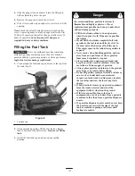
Page 13: ... you and others and can damage property Fill the fuel tank outdoors in an open area when the engine is cold Wipe up any gasoline that spills Do not fill the fuel tank completely full Add gasoline to the fuel tank until the level is 1 in 25 mm below the bottom of the filler neck This empty space in the tank allows gasoline to expand Never smoke when handling gasoline and stay away from an open flam...

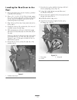
Page 14: ...rum then check the other end of the drum If there is a gap between the drum and the work surface greater than 0 010 in on either end adjust the drum proceed to step 6 If the gap is less than 0 010 in no adjustment is required 6 Remove the rear belt cover from the right side of the machine Fig 9 1 Figure 9 1 Traction drive belt cover 7 Rotate the drive pulley until the holes align with the 4 roller...

Page 15: ...of reel one click at a time until the paper is pinched lightly when inserted from the front parallel to the bedknife which results in a slight drag when paper is pulled Fig 11 or 12 Figure 13 Note Each time the adjusting screw is rotated one click clockwise the bedknife moves 0 0007 in 0 0017 cm closer to the reel Do not overtighten the adjusting screws 5 Check for light contact at the other end o...

Page 16: ...e and rest the rear end of the bar on the rear roller Fig 16 Figure 16 5 Rotate the adjusting screw until the roller contacts the front of the gauge bar 6 Adjust both ends of the roller until the entire roller is parallel to the bedknife Important When set properly the rear and front rollers will contact the gauge bar and the screw will be snug against the bedknife This ensures the height of cut i...

Page 17: ...e bar and tighten the screws 3 Ensure that the bar and reel are equal distance apart across the entire reel Note The bar is adjustable to compensate for changes in turf conditions Adjust the bar closer to the reel when the turf is extremely wet By contrast adjust the bar further away from the reel when turf conditions are dry The bar should be parallel to the reel to ensure optimum performance Adj...

Page 18: ...enter will set the parking brake The brake must be released before the traction drive is engaged Operator Presence Control Optional Fig 21 Located on the rear of the handle Push the operator presence control against the handle The operator presence control must be engaged before moving the traction drive lever or the engine will stop Reel Drive Lever Fig 22 Located on the right front corner of the...

Page 19: ... 6 Pull the recoil starter handle out until positive engagement results then pull vigorously to start the engine Important Do not pull the recoil rope to its limit or let go of the starter handle when rope is pulled out because the rope may break or the recoil assembly may be damaged 7 Close the choke as the engine warms up Stopping the Engine 1 Move the traction and reel drive controls to the Dis...

Page 20: ...re that everyone especially children and pets are clear of the work area Mowing Techniques Mow a green in a straight back and forth direction across the green Avoid circular mowing or turning the mower on a green because scuffing may occur Turn the mower off of the green by raising the cutting reel pushing the handle down and turning on the traction drum Mow at a normal walking pace Fast speed sav...

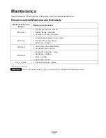
Page 21: ...ricate Fasteners check and tighten 50 Hours Fuel filter and sediment bowl clean Traction drive belts adjust Engine oil change1 100 Hours Cut off bar check adjustment Air cleaner filter service 200 Hours Combustion chamber clean Spark plug replace Valves adjust Head bolts torque Every 2 years Interlock switches replace 1Initial break in at 20 hours Important Refer to your engine operator s and serv...

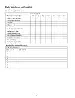
Page 22: ...interlock operation Parking brake operation Fluid level Engine oil level Air filter Clean the engine cooling fins Unusual engine noise Unusual operating noise Reel to bedknife adjustment Height of cut adjustment Grease all fittings Touch up damaged paint Notation for Areas of Concern Inspection performed by Item Date Information 1 2 3 4 5 6 7 8 ...

Page 23: ...n the front roller Fig 25 2 on the reel bearings Fig 25 2 on the drum axles Fig 26 3 on the differential Fig 26 2 on the reel countershaft bearings Fig 27 2 on the belt idler pivots Fig 28 1 Wipe each grease fitting with a clean rag 2 Pump grease into each fitting until it begins to get difficult to pump the gun Important Do not apply too much pressure or grease seals will become permanently damag...

Page 24: ...opening 7 Install the oil level gauge and wipe up any spilled oil Changing the Oil 1 Start and run the engine for a few minutes to warm the engine oil 2 Place a drain pan at the rear of machine under the drain plug Fig 29 3 Remove the drain plug 4 Push down on the handle to tip the mower and the engine backward allowing more oil to run into the drain pan 5 Install the drain plug and refill the cra...

Page 25: ...quivalent The correct air gap is 0 028 to 0 032 in 0 05 to 0 07 cm Remove the plug after every 100 operating hours and check its condition 1 Pull the wire off of the spark plug 2 Clean around the spark plug and remove it from the cylinder head Fig 32 Important Replace a cracked fouled or dirty spark plug Do not sand blast scrape or clean electrodes because engine damage could result from grit ente...

Page 26: ... over tension the belt 3 Tighten the nut to lock the adjustment 4 Install the belt cover by placing it in position 5 While maintaining a slight gap between the cover seal and the side plate install each mounting bolt until the threads engage in the insert The gap allows visual alignment of the bolts to the threaded inserts 6 After all bolts are installed tighten them until the stand offs inside th...

Page 27: ...d rear sections of the differential cover to the differential housing and slide the cover sections away to expose the belt 2 1 Figure 39 1 Differential belt 2 Idler pulley 2 Loosen the idler pulley mounting nut and pivot the idler pulley clockwise against the backside of the belt until the desired belt tension is attained Important Do not over tension the belt 3 Tighten the nut to lock adjustment ...

Page 28: ...ing the engine adjust the belt guide Fig 41 inset as follows A Engage the clutch B Loosen the capscrew securing the idler pulley and belt guide to the idler arm C Rotate the belt guide clockwise until a gap of approximately 0 06 in 0 15 cm is obtained between the guide finger and the backside of the drive belts D Tighten the capscrew and locknut securing the idler pulley and belt guide to the idle...

Page 29: ...rive Belt page NO TAG 15 Install the differential traction drive and reel drive covers Adjusting the Traction Control If the traction control does not engage or it slips during operation an adjustment is required 1 Move the traction control to the Disengaged position 2 Loosen the retainer securing the V belt cover and pivot the cover open Fig 40 3 To increase the cable tension loosen the front cab...

Page 30: ... back out the spring tension screw until the thrust washer is no longer tensioned against the bedbar Fig 46 3 On each side of the machine loosen the jam nut securing the bedbar bolt Fig 46 2 1 Figure 47 1 Jam nut 2 Bedbar bolt 4 Remove each bedbar bolt allowing the bedbar to be pulled downward and removed from the machine Save the 2 nylon and 2 stamped steel washers on each end of bedbar Fig 46 In...

Page 31: ...il spring is collapsed then back off 1 2 turn 4 Adjust bedbar refer to Adjusting the Bedknife to the Reel page 15 Backlapping the Reel 1 Remove the plug in the right reel drive cover Fig 50 1 Figure 50 1 Cover plug 2 Insert a 1 2 in socket extension connected to the backlapping machine into the square hole in the center of the reel pulley 3 Backlap according to the procedure in the Toro Sharpening...

Page 32: ... contamination use of unapproved coolants lubricants additives or chemicals etc Normal wear and tear items Normal wear and tear includes but is not limited to damage to seats due to wear or abrasion worn painted surfaces scratched decals or win dows etc Parts Parts scheduled for replacement as required maintenance are warranted for the period of time up to the scheduled replacement time for that p...

Reviews: