


Greensmaster Flex 18/21
Page 7 – 21
Cutting Unit
C. If cutting unit is equipped with a groomer, remove
LH groomer side plate (see Groomer Reel Bearing
Replacement in the Service and Repairs section of
Chapter 8 – Groomer).
D. Locate and retrieve three (3) spacers (items 4
and 5) from between reel drive plate and side plate.
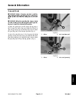
7. Remove front and rear rollers from cutting unit (see
Roller Removal in this section).
8. Support reel weight on right side of the cutting unit to
prevent it from falling. Remove two (2) cap screws and
flat washers that secure weight. Remove reel weight
from cutting unit.
NOTE: The reel bearing lock nut has left hand threads.
9. Block reel with a piece of wood to prevent reel from
turning. Remove reel bearing lock nut from right side of
reel.
10.Remove cap screw, flat washer and lock nut that se-
cures grass shield to RH side plate.
IMPORTANT: Support reel to prevent it from falling as
side plate is removed.
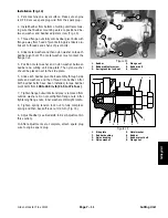
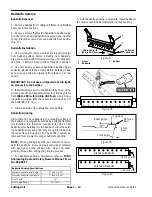
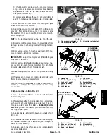
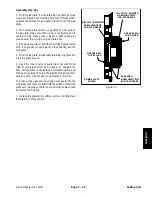
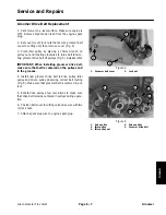
11. Remove two (2) shoulder bolts and square nuts that
secure RH side plate to crossmember (Fig. 32). Slide
RH side plate and pitch arm from reel shaft.
12.Slide cutting reel from the LH side plate and cutting
unit.
13.If necessary, remove LH side plate and pitch arm
from crossmember and grass shield.
14.Refer to Cutting Reel Service in this section for infor-
mation on reel inspection and wear sleeve and v–ring
seal service.
Cutting Reel Installation (Fig. 29)
1. Use a flat level surface or a stable work bench to
install cutting reel.
2. If separated, attach LH side plate to crossmember
with two (2) shoulder bolts and square nuts (Fig. 32).
Torque shoulder bolts from 210 to 240 in–lb (23.7 to
27.1 N–m). Make sure that LH pitch arm is installed on
bushing on side plate.
3. Apply antiseize lubricant to bearing journals of cut-
ting reel.
4. Make sure that wear sleeve and v–ring seal are prop-
erly installed on both ends of reel shaft (see Cutting Reel
Service in this section).
5. Apply grease to lips of grease seals in side plates to
ease reel installation.
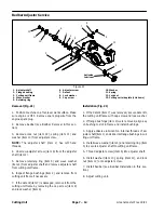
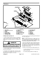
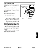
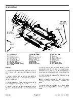
1. Cap screw w/lock washer
2. Cap screw w/flat washer
3. LH cutting reel sideplate
Figure 30
2
2
1
3
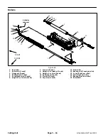
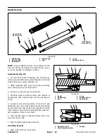
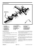
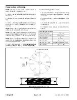
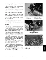
1. Flange
nut
2. Drive pulley (22 tooth)
3. Lock nut (2 used)
4. Spacer (2 used)
5. Spacer
6. Lock
washer
7. Cap
screw
8. Reel drive plate
9. Woodruff
key
10. Cap screw (2 used)
11. Flat washer (2 used)
12. Seal spacer
Figure 31
5
3
2
1
4
6
8
7
9
10
11
12
Antiseize
Lubricant
40 to 50 ft–lb
(54 to 68 N–m)
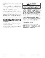
1. Crossmember
2. Shoulder bolt (4 used)
3. RH side plate
4. Square nut (4 used)
5. LH side plate
6. Nylon
bushing
7. Rubber
bushing
Figure 32
3
2
1
4
5
6
7
210 to 240 in–lb
(23.7 to 27.1 N–m)
Cutting Unit
Summary of Contents for 04022 Greensmaster Flex 21
Page 2: ...Greensmaster Flex 18 21 This page is intentionally blank ...
Page 4: ...Greensmaster Flex 18 21 This page is intentionally blank ...
Page 58: ...Greensmaster Flex 18 21 Page 5 10 Electrical System This page is intentionally blank ...
Page 83: ...Greensmaster Flex 18 21 Page 7 13 Cutting Unit This page is intentionally blank Cutting Unit ...
Page 85: ...Greensmaster Flex 18 21 Page 7 15 Cutting Unit This page is intentionally blank Cutting Unit ...
Page 111: ...Greensmaster Flex 18 21 Groomer Page 8 15 This page is intentionally blank Groomer ...


