
Greensmaster Flex 18/21
Groomer
Page 8 – 18
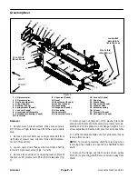
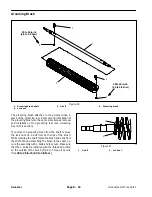
Grooming Brush
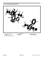
Figure 20
1. Grooming brush shaft
2. Lock
nut
3. J–bolt
4. Grooming
brush
3
1
2
4
2
3
20 to 25 in–lb
(2.3 to 2.8 N–m)
20 to 25 in–lb
(2.3 to 2.8 N–m)
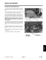
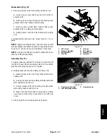
The grooming brush attaches to the groomer drive in
place of the grooming reel. Removal and installation of
the grooming brush use the same procedure as removal
and installation of the grooming reel (see Grooming
Reel in this section).
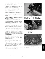
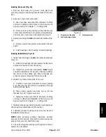
To remove the grooming brush from the shaft, remove
the lock nut and J–bolt from both ends of the brush.
While retaining the shaft, rotate the brush and slide from
the shaft. When assembling the brush to the shaft, se-
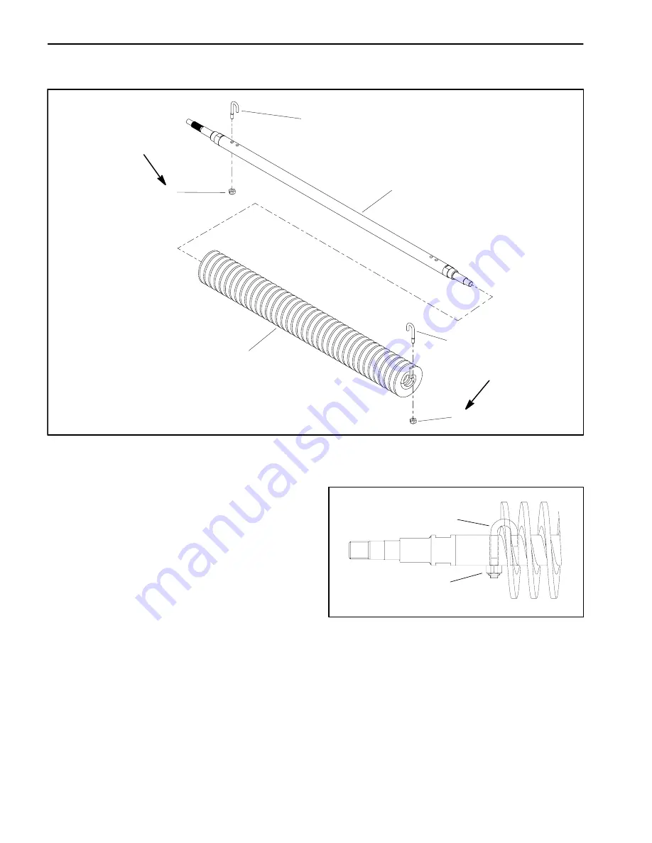
cure the assembly with J–bolts and lock nuts. Make sure
that the J–bolts are installed with the threaded portion
on the outside of the brush (Fig. 21). Torque lock nuts
from 20 to 25 in–lb (2.3 to 2.8 N–m).
1. J–bolt
2. Lock
nut
Figure 21
2
1
Summary of Contents for 04022 Greensmaster Flex 21
Page 2: ...Greensmaster Flex 18 21 This page is intentionally blank ...
Page 4: ...Greensmaster Flex 18 21 This page is intentionally blank ...
Page 58: ...Greensmaster Flex 18 21 Page 5 10 Electrical System This page is intentionally blank ...
Page 83: ...Greensmaster Flex 18 21 Page 7 13 Cutting Unit This page is intentionally blank Cutting Unit ...
Page 85: ...Greensmaster Flex 18 21 Page 7 15 Cutting Unit This page is intentionally blank Cutting Unit ...
Page 111: ...Greensmaster Flex 18 21 Groomer Page 8 15 This page is intentionally blank Groomer ...


