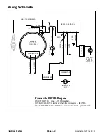


Greensmaster Flex 18/21
Page 6 – 6
Chassis and Controls
Parking Brake Cable Replacement
Removal
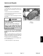
1. Park machine on a level surface. Make sure engine
is OFF. Remove spark plug wire from the engine spark
plug.
2. Disengage parking brake to release tension on the
brake cable. Remove cable ties that secure cable.
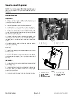
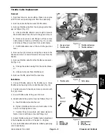
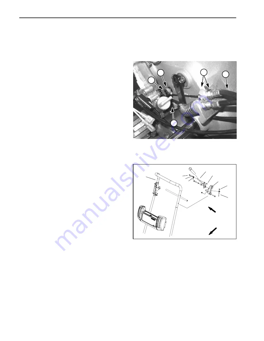
3. Remove parking brake cable from the gearbox as
follows (Fig. 4):
A. Loosen front cable jam nut and lift cable free from
casting slot on gearbox.
B. Loosen lock nut that secures gearbox brake lever
to splined gearbox shaft. Slide lever toward engine to
allow room for cable eyelet removal.
C. Remove retaining ring from the gearbox brake le-
ver.
D. Remove brake cable eyelet from brake lever.
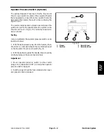
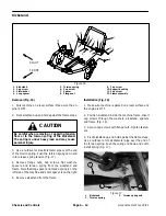
4. Remove flange head screw, spacer and lock nut that
secures brake cable eyelet to brake lever on machine
handle (Fig. 5).
5. Remove retaining ring securing the brake cable to
the brake bracket (Fig. 5). Remove cable from the
bracket.
6. Remove brake cable from the machine.
Installation
1. Secure brake cable eyelet to the brake lever on the
machine handle with flange head screw, spacer and
lock nut (Fig. 5).
2. Position cable to the brake bracket and install retain-
ing ring (Fig. 5).
3. Route brake cable to the gearbox assembly. Install
brake cable to the gearbox and gearbox brake lever as
follows (Fig. 4):
A. Position brake lever on splined gearbox shaft to
allow room for cable eyelet installation.
B. Install cable eyelet to the brake lever and secure
with retaining ring.
C. Slide brake lever toward gearbox and secure with
lock nut.
D. Attach brake cable to the casting slot on gearbox
with a washer and jam nut on each side of the slot.
4. Adjust brake cable (see Operator’s Manual).
5. Secure brake cable with cable ties.
6. Attach spark plug wire to spark plug.
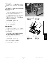
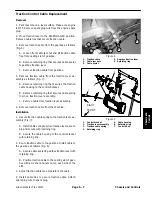
1. Brake
cable
2. Cable
eyelet
3. Cable jam nuts
4. Gearbox brake lever
5. Retaining
ring
Figure 4
1
4
2
5
3
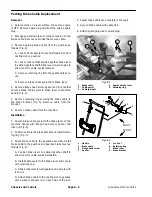
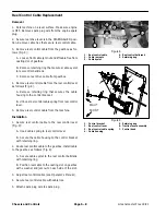
1. Handle
2. Brake
cable
3. Flange head screw
4. Spacer
5. Lock
nut
6. Retaining
ring
7. Brake
lever
8. Brake
bracket
Figure 5
4
5
8
1
3
2
6
7
FRONT
RIGHT
2
Summary of Contents for 04022 Greensmaster Flex 21
Page 2: ...Greensmaster Flex 18 21 This page is intentionally blank ...
Page 4: ...Greensmaster Flex 18 21 This page is intentionally blank ...
Page 58: ...Greensmaster Flex 18 21 Page 5 10 Electrical System This page is intentionally blank ...
Page 83: ...Greensmaster Flex 18 21 Page 7 13 Cutting Unit This page is intentionally blank Cutting Unit ...
Page 85: ...Greensmaster Flex 18 21 Page 7 15 Cutting Unit This page is intentionally blank Cutting Unit ...
Page 111: ...Greensmaster Flex 18 21 Groomer Page 8 15 This page is intentionally blank Groomer ...


