


4
Setup
Loose Parts
Note:
Use this chart as a checklist to ensure that all parts have been received. Without these parts, total setup cannot be
completed.
Description
Qty.
Use
Transport roller assembly
2
Use
when the verticutters are lowered to the shop
floor
Cotter pin
2
Use to secure transport rollers
O–ring
1
For use with reel motor bearing housing
Operator’s manual
1
Read before operating.
Parts catalog
1
Note:
Determine the left and right sides of the machine
from the normal operating position.
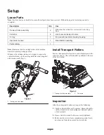
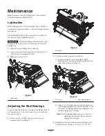
Whenever the cutting unit has to be tipped to expose the
verticutter blades, use the cutting unit kick stand (supplied
with traction unit) (Fig. 1).
1
Figure 1
1. Cutting unit kick stand
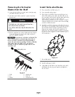
Install Transport Rollers
Secure a transport roller bracket to each sideplate pin with a
cotter pin (Fig. 2). The roller should be positined to the rear
of the vertricutter.
1
2
Figure 2
1. Transport roller assembly
2. Cotter pin
Inspection
After the cutting unit is unboxed, inspect the following:
1.
Check each end of the reel for grease. Grease should be
visibly evident in the reel bearings and internal splines
of the reel shaft.
2.
Ensure that all nuts and bolts are securely tightened.
3.
Make sure the carrier frame suspension operates freely
and does not bind when moved back and forth.


