


2
All Rights Reserved
Printed in the USA
W
2006 by The Toro Company
8111 Lyndale Avenue South
Bloomington, MN 55420-1196
Contents
Page
Introduction
2
. . . . . . . . . . . . . . . . . . . . . . . . . . . . . . . .
Introduction
2
. . . . . . . . . . . . . . . . . . . . . . . . . . . . . . . .
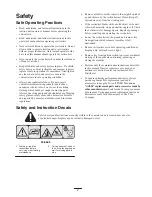
Safety
3
. . . . . . . . . . . . . . . . . . . . . . . . . . . . . . . . . . . . .
Safe Operating Practices
3
. . . . . . . . . . . . . . . . . . . .
Safety and Instruction Decals
3
. . . . . . . . . . . . . . . .
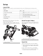
Setup
4
. . . . . . . . . . . . . . . . . . . . . . . . . . . . . . . . . . . . .
Loose Parts
4
. . . . . . . . . . . . . . . . . . . . . . . . . . . . . .
Install Transport Rollers
4
. . . . . . . . . . . . . . . . . . . .
Inspection
4
. . . . . . . . . . . . . . . . . . . . . . . . . . . . . . .
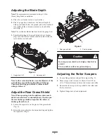
Adjusting the Blade Depth
5
. . . . . . . . . . . . . . . . . .
Adjust the Rear Grass Shield
5
. . . . . . . . . . . . . . . .
Adjusting the Roller Scrapers
5
. . . . . . . . . . . . . . . .
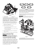
Adjusting the Transport Rollers
6
. . . . . . . . . . . . . .
Mount Verticutter Reel
6
. . . . . . . . . . . . . . . . . . . . .
Operation
7
. . . . . . . . . . . . . . . . . . . . . . . . . . . . . . . . . .
Training Period
7
. . . . . . . . . . . . . . . . . . . . . . . . . . .
Operating Tips
7
. . . . . . . . . . . . . . . . . . . . . . . . . . .
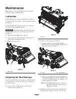
Maintenance
8
. . . . . . . . . . . . . . . . . . . . . . . . . . . . . . . .
Lubrication
8
. . . . . . . . . . . . . . . . . . . . . . . . . . . . . .
Adjusting the Reel Bearings
8
. . . . . . . . . . . . . . . . .
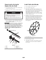
Removing the Verticutter Blades from the Shaft
9
.
Install Verticutter Blades
9
. . . . . . . . . . . . . . . . . . .
The Toro General Commercial Products Warranty
12
. .
Introduction
Read this manual carefully to learn how to operate and
maintain your product properly. The information in this
manual can help you and others avoid injury and product
damage. Although Toro designs and produces safe
products, you are responsible for operating the product
properly and safely.
Whenever you need service, genuine Toro parts, or
additional information, contact an Authorized Service
Dealer or Toro Customer Service and have the model and
serial numbers of your product ready. The model and serial
numbers are located on the side plate.
Write the product model and serial numbers in the space
below:
Model No.
Serial No.
This manual identifies potential hazards and has special
safety messages that help you and others avoid personal
injury and even death.
Danger
,
Warning
, and
Caution
are
signal words used to identify the level of hazard. However,
regardless of the hazard, be extremely careful.
Danger
signals an extreme hazard that
will
cause serious
injury or death if you do not follow the recommended
precautions.
Warning
signals a hazard that
may
cause serious injury or
death if you do not follow the recommended precautions.
Caution
signals a hazard that may cause minor or moderate
injury if you do not follow the recommended precautions.
This manual uses two other words to highlight information.
Important
calls attention to special mechanical
information and
Note:
emphasizes general information
worthy of special attention.


