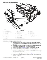
Gear Box Assembly
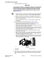
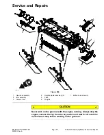
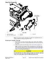
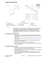
g343768
Figure 205
1.
Gear box assembly
3.
Cotter pin
5.
Input shaft
2.
Rear roller brush drive shield
4.
Clevis pin
Note:
The groomer gear box assembly is located on the opposite side of the
cutting unit from the cutting unit hydraulic motor.
Removing the Gear Box Assembly
1. Park machine on a clean and level surface, lower cutting units completely
to the ground, stop engine, engage parking brake and remove key from the
key switch.
2. Remove the groomer reel assembly (refer to
Groomer Reel (page 9–15)
).
Note:
If cutting unit is equipped with an optional powered rear roller brush,
remove the rear roller brush cover, drive belt and drive housing assembly to
service the groomer drive (refer to
Removing the Rear Roller (Figure 188)
(page 8–34)
for additional information).
CAUTION
Contact with the reel or other cutting unit parts can result in personal
injury. Use heavy gloves when handling the cutting reel.
Reelmaster
®
3100-D/3105-D
Page 9–5
Universal Groomer (Optional): Service and Repairs
20252SL Rev A
Summary of Contents for 03200 Reelmaster 3100-D
Page 4: ...NOTES NOTES Page 4 Reelmaster 3100 D 3105 D 20252SL Rev A ...
Page 6: ...g341979 Figure 1 Preface Page 6 Reelmaster 3100 D 3105 D 20252SL Rev A ...
Page 10: ...Preface Page 10 Reelmaster 3100 D 3105 D 20252SL Rev A ...
Page 20: ...Safety Safety and Instructional Decals Page 1 10 Reelmaster 3100 D 3105 D 20252SL Rev A ...
Page 44: ...Specifications and Maintenance Special Tools Page 2 24 Reelmaster 3100 D 3105 D 20252SL Rev A ...
Page 224: ...Hydraulic System Service and Repairs Page 5 148 Reelmaster 3100 D 3105 D 20252SL Rev A ...
Page 385: ......

