

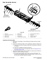

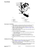
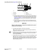


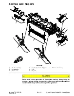

Rear Roller
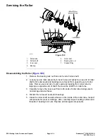
g214395
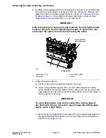
Figure 188
1.
Rear roller assembly
4.
Flange nut (2 each)
2.
Rear roller bracket
5.
Roller shim (2 each)
3.
Carriage screw (2 each)
6.
0.010 inch shim (if necessary)
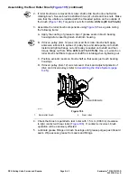
Removing the Rear Roller (
)
1. Position machine on a clean and level surface, lower cutting units, stop
engine, engage parking brake and remove key from the key switch.
2. Remove the cutting unit from the machine and place on a level working
surface. Place support blocks under bedbar to raise rear roller from work
surface.
3. Loosen two (2) flange nuts that secure the rear roller shaft to each rear roller
bracket.
4. On one of the rear roller brackets:
Note:
On cutting units equipped with optional High Height of Cut Kit, there
will be additional roller shims installed between rear roller bracket and cutting
unit side plate.
A. Remove flange nuts and carriage screws that secure rear roller bracket
and roller shims to the cutting unit side plate.
B. Remove the roller bracket and roller shims from the rear roller and cutting
unit.
5. Slide the rear roller assembly from the remaining rear roller bracket on the
cutting unit.
6. If necessary, remove the second rear roller bracket and roller shims from
the cutting unit.
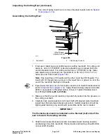
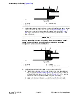
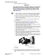
Installing the Rear Roller (
1. Place cutting unit on a level working surface.
Note:
Refer to
Cutting Unit Operator’s Manual
for number of roller shims
required for various height of cut settings.
Note:
A 0.010” shim (part number 107-4001) is available to allow for leveling
of the rear roller (refer to
Leveling Rear Roller (page 8–4)
). If necessary, this
shim would be used on one side of the rear roller and should be installed
between the rear roller bracket and roller shim.
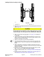
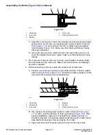
2. If both rear roller brackets were removed from the cutting unit side plate,
position brackets and roller shims to one of the side plates. Install two (2)
DPA Cutting Units: Service and Repairs
Page 8–34
Reelmaster
®
3100-D/3105-D
20252SL Rev A
Summary of Contents for 03200 Reelmaster 3100-D
Page 4: ...NOTES NOTES Page 4 Reelmaster 3100 D 3105 D 20252SL Rev A ...
Page 6: ...g341979 Figure 1 Preface Page 6 Reelmaster 3100 D 3105 D 20252SL Rev A ...
Page 10: ...Preface Page 10 Reelmaster 3100 D 3105 D 20252SL Rev A ...
Page 20: ...Safety Safety and Instructional Decals Page 1 10 Reelmaster 3100 D 3105 D 20252SL Rev A ...
Page 44: ...Specifications and Maintenance Special Tools Page 2 24 Reelmaster 3100 D 3105 D 20252SL Rev A ...
Page 224: ...Hydraulic System Service and Repairs Page 5 148 Reelmaster 3100 D 3105 D 20252SL Rev A ...
Page 385: ......