


Donaldson Company, Inc. © 1995
31
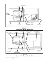
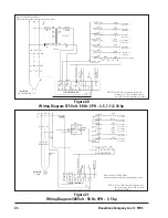
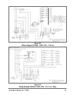
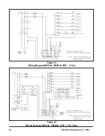
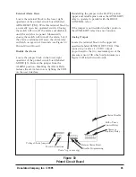
When all of the available outputs are not
required, programming the control board for
fewer outputs is accomplished by resetting the
program pin selection wire on the solid-state
control board to the correct number of solenoid
valves being used (see Figure 29 SDF Solid-State
Timer Wiring Diagram).
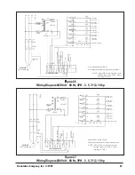
The 1TGS is an optional switch (not supplied by
Torit) and provides a means of control when the
pulse sequence is activated. Consult your local
Torit representative before using this method.
In grounded systems, neutral to control box
must be connected to L2.
Input:
105-135 VAC/50-60 Hz/1
Output Solenoids:
Type—solid-state switch
(Triac). The load is carried by and turned on
and off by the Triac. Rating–200 watts
maximum load per output.
Pulse Width (ON Time):
Factory set at 100
milliseconds (1/10 second).
OFF Time:
Adjustable–1 to 1.5 seconds
minimum, 30 seconds maximum, factory set
at 10 seconds.
Operating Temperature Range:
-20°F to 130°F.
Transient Protection:
50kW transient of
20ms duration once every 2 seconds.
Solenoid Valves:
115 volts AC at 19.7 watts
each.
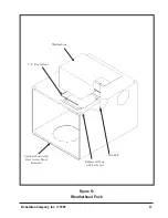
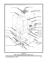
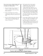
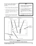
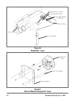
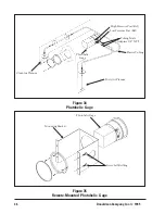
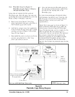
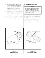
2.6.4 Magnehelic Gage (See Figure 30
Magnehelic Gage & Figure 31 Remote-
Mounted Magnehelic Gage)
Some units are supplied with an optional
Magnehelic gage where the gage, pressure taps,
and tubing have been preinstalled in our factory.
Zero and maintain the Magnehelic gage per the
operating and maintenance instructions provided
by the manufacturer of the Magnehelic gage.
For remote-mounted gages, the plastic tubing
will determine the distance away from the unit
that the gage can be located. If more tubing is
required, please contact your local Torit
representative.
Mount the remote gages as shown in Figure 31
Remote-Mounted Magnehelic Gage. Make the
connections as shown in Figure 30 Magnehelic
Gage. The high pressure port is connected to the
dirty air plenum. The low pressure port is
connected to the clean air plenum. The high and
low pressure connections are located in the
electrical compartment of the collector. Use
bulkhead fittings and mount them through the
cabinet to the electrical compartment. Zero and
maintain the gage per operating instructions.
NOTE
Do not adjust ON time unless the
proper test equipment is used.
Too much or too little ON time can
cause shortened filter element life.
Consult with your local Torit
representative.


