


5.1
GENERAL INSTRUCTIONS
IT
INSTALLATION
5
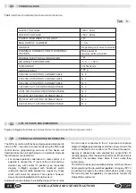
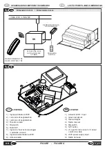
5.2
INSTALLATION OF THE RAIN SENSOR
Installation of the control unit must be made
exclusively by qualified technical personnel in
possession of the professional requisites foreseen by
the legislation in force in the country of installation..
&
The device must be connected in the room in a suitable
position depending on the distance of the actuators to be
driven, and in compliance with the safety conditions foreseen
by the legislation in force in the country of installation.
&
Do not install the control unit outside the room, subject to
atmospheric agents and do not use it in environments with a
potentially explosive atmosphere.
Installation of the rain sensor should be made outside
the building, possibly on the roof or in a similar
position.
The power unit is equipped with an input for the rain sensor
RDC/12V. The rain sensor should be installed at an angle of
about 5° ÷ 45° with respect to horizontal, and in a position
where it is not protected from rainfall.
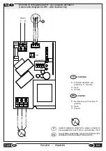
@
It is advisable to install the rain sensor before making the
electrical connections.
After completing installation of the control unit, make sure it
receives the automatic closure order correctly from the rain
14
EN
RR
INSTALLATION AND USE INSTRUCTIONS
Do not detach, displace, damage or render illegible the labels
relative to the safety of the actuators. Failure to comply with
this rule could cause serious damage to persons or objects.
The manufacturer has no liability for any damage caused by
failure to comply with this rule.
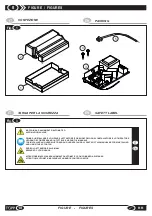
Fig.3
illustrates the safety label: it must be applied directly on
the outside of the actuator or near it and, in any case, in a
position where it can readily be seen by the installer and/or
The installer and user are informed, however, that after
installation of the actuators on the windows, their automatic
action may accidentally generate the following residual
hazard:
%
Residual hazard:
Danger of crushing or dragging parts of
the body inserted between the moving part and the fixed
part of the window.
%
Frequency of exposure:
Accidental and when the
installer or user voluntarily performs an improper action.
%
Dimensions of danger:
Normally reversible injuries.
%
Measures adopted:
1. Manual control
(remote control, or wired switch):
Obligation to ascertain that there are no persons,
animals or objects in the vicinity whose safety could be
endangered. Obligation during use of the actuator to
be in a safe control position that guarantees visual
control of the window movements.
2. Automatic control
(sensors): Obligation to apply on
the window a suitable safety warning and/or install an
acoustic/luminous warning signal in the vicinity. If the
movable part of the window is under 2,5m respect to
the floor, it would be advisable to use actuators in
according with the EN 60335-2-103 directive or shield
the dangerous parts with suitable safety. In order to
assist installers in applying the European regulations
and directives regarding the safety and use of the
motorized actuators, a special downloadable guide is
available from our website www.topp.it.
3. Safety warnings
: They are included in the actuator
package and must be applied directly to the outside of
the actuator or near it and, in any case, in a position
visible to the installer or user.
&
The operators must be informed about all possible risks of
accidents, the safety devices for their protection, the general
rules for accident prevention foreseen by the international
directives and laws in force in the country in which the power
unit is used. The behavior of the operators must in every case
comply strictly with the rules for accident prevention in force
in the country in which the unit is used.
&
If the window is accessible or is installed at a height from
the ground of less than 2.5 m, if an untrained user should
tamper with it or with the remote control, provide the system
with an emergency circuit breaker that acts automatically to
prevent the risk of crushing or dragging the body between the
moving parts and the fixed part of the window.
&
It is strictly prohibited to remove or alter the labels applied
by the manufacturer on the power unit.
&
This appliance may not be used by persons (children
included) with reduced physical, sensorial or mental
capacities, or inexpert people, unless they are supervised
and taught how to use it by a person responsible for their
safety. Children must be controlled to make sure they do not
play with the appliance.
IT
SAFETY
4
4.1
GENERAL INSTRUCTIONS
4.2
SAFETY DEVICES
4.3
SAFETY PLACE
4.4
RESIDUAL HAZARDS
Protection against electrical dangers:
The power unit is
protected against electrical danger from direct and indirect
contact.
The protection measures against direct contact serve to
protect individuals from the risks deriving from active parts
that are normally powered. The protection measures against
indirect contact serve to protect persons from the risks
deriving from conductive parts, which are normally insulated,
but could be powered due to breakdown (loss of insulation).
The protection measures adopted are:
1.
insulation of the active parts with a body in plastic metal;
2.
enclosure with an adequate degree of protection;
3.
passive protection consisting of the use of doubly
insulated parts also known as class II parts, or parts with
equivalent insulation.
Summary of Contents for RR
Page 23: ......


