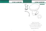
background image

16

Lavac Installation 

Handle position (angle of operation) and/or outlet
direction can be varied by rotating pump body
(26) relative to back cover (35) (See exploded
diagram p.8).
If back cover (35) is rotated ensure air bleed hole
in back cover is re-drilled at lowest point.

DIRECTION OF

OUTLET

therefore all hose clips must be

tight.

8. An important part of the Lavac

installation is the air bleed valve

which has to be located at the top

of the loop of the inlet pipe. Drill a

5mm (

1/18

”)diameter hole at the

top of the curve of the inlet pipe If

the top of the inlet pipe is in a

clothing locker, ensure that the

clothes do not obstruct the air

bleed valve. Similarly, if the hose

is hard up below the deck, drill the

hole slightly to one side at the top

of the loop. For installations on or

above the water line, insert the

white plastic bleed plug.

For installations below the water

line, use the black plastic plug.

(Set of bleed plugs TLZ9251).

9. Attach the self-adhesive oper-

ating instructions to the bulkhead

near the pump. We recommend

that a suitable rubber stop is

placed on the bulkhead behind the

Lavac unit to avoid possible dam-

age to the lid when opened.

inlet and, particularly, the outlet

hoses. If it is completely unavoid-

able to use right angled fittings in

the outlet hose, then rigid plastic fit-

tings should be used having an

inside radius of not less than 31mm

(2“). Do not use sharp angled

plumbers fittings which can easily

cause a blockage.

4. Establish a position for the pump

where the pump inlet is no lower

than the bowl top.

5. Bolt or screw the pump in posi-

tion using 6mm (¼“) diameter bolts

or screws ensuring that the flow

arrow on the pump is vertically up

or certainly not more than 45° from

the vertical.

IF THE PUMP IS MOUNTED IN

ANY OTHER WAY THE INSTALLA-

TION WILL BE INEFFICIENT IN

OPERATION AS THE INLET VALVE

CANNOT SEAL EFFECTIVELY.

6. Cut the 38mm (1½“) diameter

outlet hose to the lengths required.

Be sure to allow enough hose from

the top of the pump to take the loop

above the waterline at maximum

heel of the boat. For motor vessels

this is high enough at maximum

angle of roll. Attach the two cut

lengths of hose from the bowl to the

bottom (inlet) of the pump and from

the top of the pump (outlet) to the

outlet seacock.

7. Connect the 19mm (¾“) bore

inlet hose to the bowl inlet, having

allowed for a loop similar to the outlet

(see point 6) and attach the inlet

hose to the inlet seacock.

PEASE NOTE: It is absolutely

essential that all joints are 100%

sealed. No air leakage is permissible

Summary of Contents for BLAKES LAVAC Popular 4610-000

Page 1: ...diagram 8 Parts list Accessories specification 9 Electric Pump Exploded diagram 10 Parts list Accessories specification 11 Zenith and Popular Spares kits 12 Lavac Operation diagrams 13 Installation S...

Page 2: ...n advice from sailors around the world concerning their requirements for marine equipment and our current range is a result of this ongoing com mitment If you have any comments or help ful hints that...

Page 3: ...ast making it impractical this edition of the Lavac owners handbook now gives guid ance on holding tanks see pages 18 Features z Easy and versatile in installation z Can be mounted under bunk or locke...

Page 4: ...UPDATE New Thermo set seal 11 introduced July 1993 with no joins or weld points Cross section below showing longer sealing lip conforms bet ter to contact surface seat or bowl for improved vacuum PROD...

Page 5: ...11 4 D 410mm 16 2 Lavac Zenith Zenith Components Diagram No Part No Description 1 TBB7215 x 4 M6 Nuts 2 TLZ9021 x 4 Pan bolt washers small TLZ9022 x 4 Pan bolt washers large 3 TLZ9022 x 4 M6 x 35 Pan...

Page 6: ...6 Exploded diagram of the Lavac Popular...

Page 7: ...16 4 Lavac Popular Popular Components Diagram No Part No Description 4 TLZ9005 Pedestal base 5 TLZ9010 Pan base joint 51 TLZ8015 x 4 M6 x 50 Pan bolt TLZ8010 x 4 Plastic covers TLZ8022 x 4 Plastic wa...

Page 8: ...Bulkhead plate and shroud for the U D pump makes a neat flush installation Spares No TLZ9460 see installation diagram on p 15 U D Pump Handle Position T A Pump Handle Position Exploded diagram of Han...

Page 9: ...valve hand TLZ9335 Inlet valve plate 23 TLZ9320 Front cover 24 TLZ9325 Front cover seal 25 TLZ9125 Eye bolt nut 26 TLZ9100 Top cover complete with valves 27 TLZ9340 Outlet valve 28 TLZ9345 x 2 Outlet...

Page 10: ...10 Exploded diagram of the electric pump 12 24 Volt...

Page 11: ...0 Diaphragm 21 TLZ9175 x 8 2BA x 1 Bolts TLZ9181 x 8 2BA nuts 22H TLZ9330 Inlet valve hand TLZ9335 Inlet valve plate 23 TLZ9320 Front cover 24 TLZ9325 Front cover seal 25 TLZ9125 Eye bolt nut 26 TLZ91...

Page 12: ...nd lid 11 Handbook TLZ0951 TLZ0956 TLZ9010 TLZ9035 TLZ9054 TLZ9060 TLZ9065 TLZLIT 1 1 1 2 2 2 1 1 1 1 2 2 2 1 Zenith spares kits Lavac Popular Description Part No Hand pump kit 12 or 24V electric pump...

Page 13: ...13 Lavac operation...

Page 14: ...d to the hull slightly greater in diame ter than the seacock flange and 13mm to 19mm to thick see fig 1 To ensure watertight joints on Fig 1 INLET SEACOCK WITH STRAINER CHAMFER EDGE WOODEN PAD GRP HUL...

Page 15: ...er remaining in the bowl Two valves with different sized holes are provided Spares No TLZ9251 the larger the hole the less water remains in the bowl 4 DISCHARGE SEACOCK 5 BOWL The outlet at the rear o...

Page 16: ...opened inlet and particularly the outlet hoses If it is completely unavoid able to use right angled fittings in the outlet hose then rigid plastic fit tings should be used having an inside radius of n...

Page 17: ...1 second and 10 minutes 3 Ensure when mounting the pump that the flow arrows are facing upwards Do not mount in a horizontal position Also ensure that the pump is no lower than the top of the bowl 4...

Page 18: ...rths x days between pump out x Y gallons capacity of tank zFor recirculating systems factor Y 0 5 zFor fresh water flush systems factor Y 2 5 These calculations assume low water use toilets are being...

Page 19: ...it is practical to install a high tank Why not consider for exam ple a full height floor to roof bulkhead tank This can be in conjunction with either sea water or fresh water flush systems Diverted Pu...

Page 20: ...if draw is more than 36 below toilet or vented loop required if toilet is below waterline Useful statistics z One cubic foot contains 6 gallons z One gallon contains 1 6 cubic feet z One gallon of wat...

Page 21: ...and or Electric Self pump out inboard pump Hand or Electric Flush water intake C B HOLDING TANK LAVAC TOILET Diverter Valve Fig 3 3 For craft requiring toilet dis charge to sea or holding tank and pu...

Page 22: ...oop 5 Seacock Fig 5 To sea LAVAC TOILET 2 WAY VALVE PUMP From Bilge Shower Basin Etc DISCHARGE Holding Tank Accessories 1 Two way valve Spares No TLZ9310 The two way valve in the systems above shows h...

Page 23: ...Electric pump operation 1 To flush the toilet close the seat and lid and press the push but ton fully in and release it 2 The Lavac electric pump whether incorporated in the Lavac electric toilet or...

Page 24: ...Day to day points to remember 1 Ensure that the operating instructions are mounted where your guests will see them 2 Always fully flush the toilet 3 Occasionally flush through with soapy water 4 Put...

Page 25: ...o ring 24 Maintenance Perishable parts Replacing the seat and lid seals 1 Hook one end of the seal under the rim of the lid stretch the seal around the rim and clip under all way round Photo 1 2 Repe...

Page 26: ...in reverse order replacing all the stainless steel screws 21 28 When re assembling the pump ensure all screws are tight If air can be drawn into the pump the toilet will not operate To prevent leaking...

Page 27: ...oo large In this instance it may be necessary to fit a non return valve in the inlet hose just above the water line This maintains a head of water to facilitate the initial syphoning of flushing water...

Page 28: ...the hose this job is much easier Pump very rapidly to see if you can regain prime or remove front cover and pour as much water as possible into the pump and retry Loss of prime may be due to lower val...

Page 29: ...d inlet flap valve and if this is replaced by the normal hand pump valve it can though not invariably detract from pump efficiency Please check that the arrow on the pump is pointing vertically upward...

Page 30: ...hould be held below the pump whilst doing this as the contents of the pump will escape Note the old Mark 3 pump has fixing screws to the front cover Check that the inlet and outlet valves are not bein...

Page 31: ...31 Note...

Reviews: